
Related Manuals for Weishaupt WWP LA 60-A R


Summary of Contents for Weishaupt WWP LA 60-A R
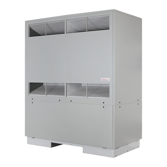
- Page 1 Installation and operating instructions Weishaupt Air-to-water heat pump for outdoor installation WWP LA 60-A R 83321302 03/2021...
-
Page 3: Table Of Contents
Installation and operating instructions WWP LA 60-A R Table of contents Safety notes ............................. 2 Symbols and markings ....................2 Intended use ........................ 2 Legal regulations and directives................2 Energy-efficient use of the heat pump..............3 Intended use of the heat pump ..................... 4 Area of application...................... -
Page 4: Safety Notes
Installation and operating instructions WWP LA 60-A R 1 Safety notes Safety notes Symbols and markings Particularly important information in these instructions is marked with CAUTION! and NOTE. ACHTUNG CAUTION Immediate danger to life or danger of severe personal injury or significant damage to property. -
Page 5: Energy-Efficient Use Of The Heat Pump
Installation and operating instructions WWP LA 60-A R 1 Safety notes Energy-efficient use of the heat pump By operating this heat pump, you are helping to protect the environment. A prerequisite for energy-efficient operation is the correct design of the heat source system and heating system. -
Page 6: Intended Use Of The Heat Pump
Installation and operating instructions WWP LA 60-A R 2 Intended use of the heat pump Intended use of the heat pump Area of application The air-to-water heat pump is to be used exclusively for the heating and cooling of heating water. It can be used in new or existing heating systems. -
Page 7: Scope Of Supply
Installation and operating instructions WWP LA 60-A R 3 Scope of supply Scope of supply Basic device The heat pump contains the components listed below. The refrigeration circuit is "hermetically sealed" and contains the fluorinated refrigerant R407C incorporated in the Kyoto protocol. Information on the GWP value and CO equivalent of the refrigerant is available under “Device information”. -
Page 8: Heat Pump Manager
Installation and operating instructions WWP LA 60-A R 3 Scope of supply Heat pump manager The heat pump manager included in the scope of supply must be used to operate the air-to-water heat pump. The heat pump manager is a convenient electronic regulation and control device. It controls and monitors the entire heating system based on the outside temperature, as well as domestic hot water preparation and safety systems. -
Page 9: Accessories
Installation and operating instructions WWP LA 60-A R 4 Accessories Accessories External 4-way reversing valve The external 4-way reversing valve (Y12) enables optimised heating and cooling operation of the reversible air-to-water heat pump. Switching the direction of flow ensures an optimal flow through the heat exchanger in the heat pump in heating operation as well as in the opposite direction in cooling operation. -
Page 10: Transport
Installation and operating instructions WWP LA 60-A R 5 Transport Transport ACHTUNG CAUTION When transporting the heat pump, ensure that it is not tilted by more than 45° (in any direction). A pallet should be used for transportation to the final installation location. The basic device can be transported with a lift truck or a crane. -
Page 11: Installation
Installation and operating instructions WWP LA 60-A R 6 Installation Installation General information The device must be installed on a permanently even, smooth and horizontal surface. The entire frame should be in direct contact with the ground in order to ensure an adequate soundproof seal, to prevent the water-bearing components from becoming too cold and to protect the inside of the device from small animals. -
Page 12: Condensate Pipe
Installation and operating instructions WWP LA 60-A R 6 Installation ACHTUNG CAUTION In cases of installation close to walls, there may be more contamination in the intake and air outlet area due to the air flow. The colder outside air outlet should discharge in such a way as to not increase the heat losses in heated neighbouring rooms. -
Page 13: Installation
Installation and operating instructions WWP LA 60-A R 7 Installation Installation General information The following connections need to be established on the heat pump: Heating system flows and returns Condensate drain Control cable to the heat pump manager ... - Page 14 Installation and operating instructions WWP LA 60-A R 7 Installation Note: For operation of the heat pump with the 4-way reversing valve, it is essential to set up the hydraulic connections according to the instructions included in the scope of supply of the valve.
-
Page 15: Electrical Connection
Installation and operating instructions WWP LA 60-A R 7 Installation Electrical connection 3 lines/cables must be routed to the heat pump in total: A standard 5-core cable is used to connect the heat pump to the power supply. The cable must be provided on-site. The conductor cross section is selected in accordance with the power consumption of the heat pump (see appendix Device Information) and the applicable VDE (EN) and VNB regulations. -
Page 16: Commissioning
Commissioning General information To ensure that commissioning is performed correctly, it should only be carried out by an after-sales service technician authorised by the manufacturer (Weishaupt technician). Under certain conditions, this may be associated with an additional warranty service. Preparation The following items must be checked prior to commissioning: All of the heat pump connections must be installed as described in chapter 7. -
Page 17: Cleaning/Maintenance
Installation and operating instructions WWP LA 60-A R 9 Cleaning/maintenance Cleaning/maintenance Care To protect the paintwork, avoid leaning anything against the device or putting objects on the device. External heat pump parts can be wiped with a damp cloth and commercially available domestic cleaner. -
Page 18: Cleaning The Air System
Installation and operating instructions WWP LA 60-A R 9 Cleaning/maintenance Cleaning the air system The evaporator, fan and condensate drain should be cleaned of contamination (leaves, twigs, etc.) before each new heating period. ACHTUNG CAUTION Before opening the device, ensure that all electric circuits are disconnected from the power supply. -
Page 19: Faults/Troubleshooting
Installation and operating instructions WWP LA 60-A R 10 Faults/troubleshooting 10 Faults/troubleshooting This heat pump is a quality product and is designed for trouble-free operation. In the event that a fault should occur, it will be indicated on the heat pump manager display. -
Page 20: Decommissioning/Disposal
Installation and operating instructions WWP LA 60-A R 11 Decommissioning/disposal 11 Decommissioning/disposal Before removing the heat pump, disconnect it from the power source and close all valves. The heat pump must be dismantled by trained personnel. Observe all environmental requirements regarding the recovery, recycling and disposal of materials and components in accordance with all applicable standards. -
Page 21: Device Information
Installation and operating instructions WWP LA 60-A R 12 Device information 12 Device information Type and order code WWP LA 60-A R Design Heat source 2.1 Version Universal, reversible 2.2 Controller WPM wall-mounted 2.3 Thermal energy metering Integrated 2.4 Installation location Outside 2.5 Performance level... - Page 22 Installation and operating instructions WWP LA 60-A R 12 Device information Additional model features 8.1 Type of defrosting (according to need) Reverse circulation 8.2 Condensate tray frost protection/water in device Heated/yes protected against freezing 8.3 Max. operating overpressure (heat source/heat sink) 8.4 Hydraulic four-way reversing valve (external)
-
Page 23: Dimension Drawings
Installation and operating instructions WWP LA 60-A R 13 Dimension drawings 13 Dimension drawings 13.1 Dimension drawing Connection method: only heating Connection method: heating and cooling 1 (A) Heating water flow, output from heat pump R2 Connection A of ext. 4-way reversing valve R2... -
Page 24: Diagrams
Installation and operating instructions WWP LA 60-A R 14 Diagrams 14 Diagrams 14.1 Characteristic curve, heating Heat output in [kW] Water outlet temperature in [°C] EN 14511 A7 W35...30 6,0 m³/h A7 W45...40 5,8 m³/h 2-compressor operating mode A7 W55...47 3,4 m³/h... -
Page 25: Characteristic Curve, Cooling
Installation and operating instructions WWP LA 60-A R 14 Diagrams 14.2 Characteristic curve, cooling Cooling capacity in [kW] Water outlet temperature [°C] Conditions: Cooling water flow A35 W23-18 10.2 m³/h A35 W12-7 8.3 m³/h 2-compressor operating mode 1-compressor operating mode Caution! Observe operating limits diagram Air intake temperature in [°C]... -
Page 26: Operating Limits Diagram, Heating
Installation and operating instructions WWP LA 60-A R 14 Diagrams 14.3 Operating limits diagram, heating 6.0 m³/h 3.4 m³/h Water outlet (+0/-2 K) *Water inlet -30 -25 -20 -15 -10 Heat source inlet temperature [°C] *For air-to-water heat pumps, the minimum heating water temperature is the minimum return temperature Subject to changes and errors 452163.66.99 ·... -
Page 27: Operating Limits Diagram, Cooling
Installation and operating instructions WWP LA 60-A R 14 Diagrams 14.4 Operating limits diagram, cooling Water outlet (+/- 2 K) The values are valid for the specified minimum cooling water flow. Heat sink inlet temperature [°C] Subject to changes and errors 452163.66.99 ·... -
Page 28: Integration Diagrams
Installation and operating instructions WWP LA 60-A R 15 Integration diagrams 15 Integration diagrams 15.1 Sample system diagram The system example is a non-binding draft design with no claims of completeness. Final system design must be carried out in consultation with an expert planner. -
Page 29: Circuit Diagram
Installation and operating instructions WWP LA 60-A R 15 Integration diagrams 15.2 Circuit diagram 452163.66.99 · 03/2021 · Rei 8332132... -
Page 30: Circuit Diagram, Extension Module
Installation and operating instructions WWP LA 60-A R 15 Integration diagrams 15.3 Circuit diagram, extension module 24V AC 24 V AC on-site L PE N L PE N L PE N L PE N (5)NO1 (6)NO2 (7)NO3 to WPM 6.0 X1.2... - Page 31 Installation and operating instructions WWP LA 60-A R 15 Integration diagrams 452163.66.99 · 03/2021 · Rei 8332132...
- Page 32 Max Weishaupt GmbH · 88475 Schwendi Weishaupt close by? Addresses, telephone numbers etc. can be found at www.weishaupt.de We reserve the right to make changes. All rights reserved. The complete program: Reliable technology and prompt, professional service W Burners up to 700 kW...
Need help?
Do you have a question about the WWP LA 60-A R and is the answer not in the manual?
Questions and answers