Table of Contents
Advertisement
Quick Links
PROFESSIONAL AMPLIFIER SERIES | 2 RU
INSTALLATION MANUAL
INSTALLATION GUIDE / USER MANUAL
ProA1000.1•ProA1000.1D•ProA1000.2•ProA1000.2D
00
ProA12
Please visit www.originpro.com or scan the QR code using your smart device for the most
up to date safety information and use instructions for this product.
BRAND NAME
IP500.2 • IP800.2
IP500.4 • IP800.4
00
.1•ProA12
.1D•ProA12
00
00
.2•ProA12
.2D
Advertisement
Table of Contents

Related Manuals for Origin PRO 2 RU Series


Summary of Contents for Origin PRO 2 RU Series
- Page 1 BRAND NAME PROFESSIONAL AMPLIFIER SERIES | 2 RU INSTALLATION MANUAL INSTALLATION GUIDE / USER MANUAL ProA1000.1•ProA1000.1D•ProA1000.2•ProA1000.2D IP500.2 • IP800.2 IP500.4 • IP800.4 ProA12 .1•ProA12 .1D•ProA12 .2•ProA12 Please visit www.originpro.com or scan the QR code using your smart device for the most up to date safety information and use instructions for this product.
- Page 2 Please read the following important technical, safety and environmental notices before installing and using your amplifier. Technical & Safety Notices Safety and Environmental Notices Note: The intent of the lightning flash with arrowhead All reasonable design and engineering steps have been taken to en- symbol in a triangle is to alert the user to the presence of sure that these amplifiers always perform satisfactorily in their in- Technical and Safety Notices...
- Page 3 Important Safety Instructions Environmental Statement 1. Read these instructions. This product complies with international directives, including but not 2. Keep these instructions. limited to the Restriction of Hazardous Substances (RoHS) in electrical 3. Heed all warnings. and electronic equipment, the Registration, Evaluation, Authoriza- 4.
-
Page 4: Table Of Contents
1. INTRODUCTION 2. PRODUCT OVERVIEW 3. AMPLIFIER CHANNELS 4. SIGNAL INPUT & OUTPUT OVERVIEW 5. ORIGIN PRO AMPLIFIER WEB APP | USER INTERFACE CONFIGURATION 6. AMPLIFIER CONNECTIONS 7. AMPLIFIER OPERATION 8. 2RU AMPLIFIER SERIES SPECIFICATIONS 9. UL CERTIFICATION & SAFETY AGENCY COMPLIANCE 10. -
Page 5: Introduction
Thank you for purchasing an Origin PRO amplifier. Please read this manual fully before installing and using an amplifier. Origin PRO Amplifiers have been designed to provide configurable, consistent and reliable high performance audio power amplification for residential, commercial and entertainment applications. -
Page 6: Product Overview
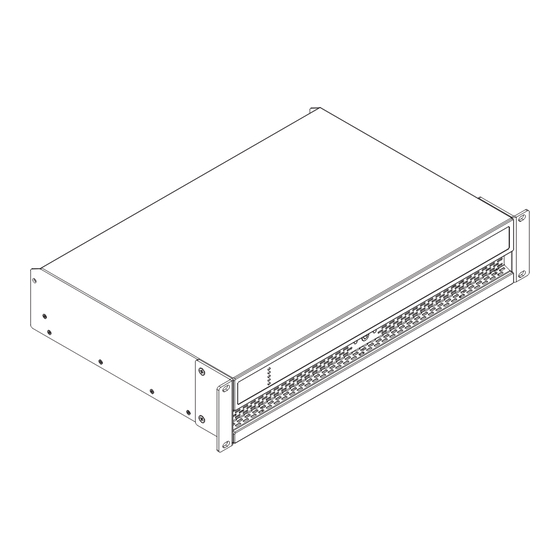
2. PRODUCT OVERVIEW 2.1. CARTON CONTENTS Origin PRO Amplifiers are shipped in a cardboard carton containing the amplifier unit, a power cable appropriate for the sales territory, an accessory pack, and a quick start guide. The full contents are listed below. - Page 7 Installation DIAGRAM 2A 4. Installation Origin PRO 2RU Amplifier dimensions 4.1 Amplifier Location [AMP NAME] amplifiers are shipped with rack “ears” attached and are primarily intended for standard (19 inch)equipment rack installation. If not to be installed in an equipment rack, [AMP NAME] amplifiers can be placed free-standing on a flat 2 &...
-
Page 8: Amplifier Channels
3. AMPLIFIER CHANNELS These Origin Pro Amplifiers are full rack width, 2U format power amplifiers that can drive both conventional low impedance (Lo-Z, 4Ω to 8Ω) loudspeakers and high impedance (Hi-Z, 70V/100V) transformer coupled loudspeakers. They provide four analog inputs, one stereo S/PDIF digital input, and either two or four outputs (Lo-Z mode), or one or two outputs (Hi-Z or Lo-Z BTL mode). -
Page 9: Signal Input & Output Overview
SECTION 6 of this manual Origin PRO Amplifiers incorporate a front panel mounted power button. Press the button once to switch the amplifier on or off. Amplifier power management behavior can be configured via the Origin PRO amplifier web app SETTINGS Menu described in SECTION 5 of this manual. -
Page 10: Origin Pro Amplifier Web App | User Interface Configuration
To connect the amplifier to a TCP/IP network using a wired connection (Ethernet) follow the steps below. 1. Use an Ethernet cable to connect the Origin PRO Amplifier rear panel Network Control socket to a free socket on a network rout- er or switch, or directly to an Ethernet equipped laptop or desktop computer. - Page 11 The Origin PRO amplifier web app interface will open to enable amplifier configuration as required. 4. Select the Origin PRO amplifier web app >SETTINGS TAB followed by WIFI > WIFI MODE > CLIENT to configure the amplifier to connect to the required WiFI network. The WiFi network name and password will be required.
- Page 12 5.3 CONFIGURATION MENUS Opening a web browser that is network connected to an Origin PRO amplifier initially displays the Origin PRO amplifier Dash- board illustrated in DIAGRAM 5A. The Dashboard is the ‘home’ page from which all other configuration options can be accessed.
- Page 13 5.3 CONFIGURATION MENUS DIAGRAM 5A Configuration Dashboard display - Continued SCROLL DOWN ADJUST VOLUME ZONE A ADJUST VOLUME ZONE B...
- Page 14 5.3.1 INPUT TAB The INPUT TAB provides the following configuration parameters for each amplifier input channel: • Input name • Mono/Stereo selection • Input sensitivity • High-pass filter • Gain trim • Five band equalization The INPUT TAB also enables input signals to be mixed and routed to specific amplifier zones. The mix function enables any amplifier input, including stereo or split mono S/PDIF inputs, to be grouped with any other input or inputs to create multiple predefined mixes.
- Page 15 5.3.1 INPUT TAB DIAGRAM 5B Input Tab display (Inputs 1 & 2 only shown) INPUT TYPE SELECTED TYPE TO EDIT INPUT NAME MONO OR SELECT SELECT INPUT STEREO SENSITIVITY INPUT TAB SELECTED A pink noise or sine wave audio signal generator, appropriate for audio system testing and set up, can also be enabled, disabled, and adjusted for gain and frequency via the INPUT TAB.
- Page 16 5.3.1 INPUT TAB DIAGRAM 5B - Continued Input Tab display - Continued (Inputs 2 & 3 only shown) SCROLL DOWN STEREO SELECTED (EXAMPLE) OPEN TO ADJUST INPUT GAIN OPEN TO ADJUST INPUT TAB SELECTED Note: When adjusting Input Gain, the input level display should remain GREEN. If it displays RED, the input Gain should be reduced.
- Page 17 5.3.1 INPUT TAB DIAGRAM 5C Input 2 Gain/Trim & EQ display ADJUST INPUT GAIN ADJUST REQUIRED EQ STAGES REQUIRED EQ STAGES SELECTED Note: When adjusting Input Gain, the input level display should remain GREEN. If it displays RED, the input Gain should be reduced.
- Page 18 5.3.1 INPUT TAB DIAGRAM 5D Input Mix display MIX FUNCTION SELECTED TYPE TO EDIT MIX NAME ADJUST MIX INPUT 1 LEVELS ADJUST MIX INPUT 2 LEVELS INPUT TAB SELECTED...
- Page 19 5.3.2 ZONE TAB The ZONE TAB enables installation zones to be defined and named, and provides access to further sub-menus. - Zones might be bar or restaurant areas for example, or different rooms in a home. For all Zone Tab menus, the installation zone under configuration is selected by highlighting one of the zone identifiers (A, B, C or D) at the top of the display.
- Page 20 5.3.2 ZONE TAB DIAGRAM 5E Zone Tab display ZONE SELECTED TYPE TO EDIT ZONE NAME MONO OR SELECT STEREO ADJUST ZONE VOLUME SELECT ZONE INPUT CONFIGURE ZONE VOLUME OPTIONS CONFIGURE ZONE RESTRICTIONS CONFIGURE ZONE COMPRESSOR ZONE TAB SELECTED...
- Page 21 5.3.2 ZONE TAB DIAGRAM 5F Zone Source menu display SELECT ZONE OPEN FOR PRIMARY INPUT OPTIONS SELECT PRIMARY INPUT OPTIONS OPEN FOR PRIORITY INPUT OPTIONS...
- Page 22 • The VOLUME MENU allows minimum and maximum zone volume limits to be set, and enables external GPIO volume control to be applied to individual zones. The GPIO configuration menu can be found under the SETTINGS TAB, and notes on connecting an external volume control via the GPIO interface can be found in Section 5.5 of this manual.
- Page 23 5.3.3 OUTPUT TAB The OUTPUT TAB enables amplifier outputs to be named, linked to zones, and provides access to DELAY, EQUALIZER and SPEAKER PRESET menus. - DIAGRAM 5G illustrates the OUTPUT TAB display. - For all OUTPUT TAB menus, the amplifier output under configuration is selected by highlighting one of the output identifiers (1, 2, 3 or 4) at the top of the display.
- Page 24 5.3.3 OUTPUT TAB DIAGRAM 5G Output Tab display SELECT OUTPUT TYPE TO EDIT OUTPUT NAME ADJUST OUTPUT SIGNAL DEFINE OUTPUT ROUTING ENABLE AND CONFIGURE OUTPUT DELAY IF REQUIRED ENABLE AND CONFIGURE OUTPUT EQ IF REQUIRED CONFIGURE & MANAGE SPEAKER PRESETS OUTPUT TAB SELECTED...
- Page 25 5.3.3 OUTPUT TAB OUTPUT ROUTING MENU OUTPUT DELAY MENU...
- Page 26 5.3.3 OUTPUT TAB OUTPUT EQ MENU SPEAKER PRESET MENU...
- Page 27 • The EQUALIZER menu enables parametric equalization to be applied to individual amplifier outputs. Equalizer settings config- ured for one amplifier output can be copied and applied to other outputs. • The SPEAKER PRESET menu enables a set of speaker parameters to be adjusted, and preset configurations to be created, exported, imported or cleared.
- Page 28 5.3.3 OUTPUT TAB DIAGRAM 5H Speaker Preset Parameters SELECT OUTPUT SELECT IMPORT PRESET SELECT TO CONFIGURE SELECT TO CONFIGURE SELECT TO CONFIGURE SELECT TO CONFIGURE SELECT TO CONFIGURE SCROLL DOWN TO SELECT MORE* *LIMITER, OUTPUT MODE...
- Page 29 5.3.3 OUTPUT TAB DIAGRAM 5I Speaker Preset: Import File Selection OUTPUT SELECTED...
- Page 30 5.3.3 OUTPUT TAB DIAGRAM 5J Speaker Preset EQ Parameter Adjustment SELECT OUTPUT ADJUST SELECTED EQ SELECT TO CONFIGURE SELECT TO CONFIGURE SELECT TO CONFIGURE SELECT TO CONFIGURE SELECT TO CONFIGURE SCROLL DOWN FOR PARAMETRICS...
- Page 31 5.3.4 SPEAKER PRESET MENU PARAMETERS • The CROSSOVER & GAIN preset menu enables high or low-pass crossover filters and gain adjustment to be applied to individual amplifier outputs. • The SPEAKER EQ preset menu enables parametric equalization to be applied to individual amplifier outputs. •...
- Page 32 Diagrams 5N & O illustrate the creation and management of speaker preset libraries. • The SECURITY menu enables a password to be set in order to protect against unauthorized access to the Origin PRO amplifier web app.
- Page 33 5.3.5 SETTINGS TAB DIAGRAM 5L Settings Tab Menu SELECT DESIRED MENU SETTINGS TAB SELECTED...
- Page 34 5.3.5 SETTINGS TAB DIAGRAM 5M FIRMWARE UPDATE selection button, found inside Device Menu FIRMWARE UPDATE SELECTED...
- Page 35 5.3.5 SETTINGS TAB DIAGRAM 5N Speaker Library Creation and Management CREATE LIBRARY SELECTED...
- Page 36 5.3.5 SETTINGS TAB DIAGRAM 5O Speaker Library Import Option CLICK TO LOAD .ZCL FILE IMPORT LIBRARY SELECTED...
- Page 37 • The POWER MANAGEMENT menu enables various automatic switch-on options to be engaged. The Power Management menu also offers timed Standby and Mute functions. • The OUTPUT ROUTING menu enables specified inputs or zones to be routed to the amplifier S/PDIF outputs. The output level can also be adjusted.
- Page 38 5.4 SETUP AND SIGNAL ROUTING Thanks to their network based configuration features, Origin PRO amplifiers offer considerable versatility in terms of sources, signal routing, installation zones and output modes. Inputs can be freely assigned to installation zones, and those zones assigned freely to the available amplifier outputs in either Lo-Z or Hi-Z modes.
- Page 39 5.4.1 INPUT SETUP Open the configuration Dashboard and select the Input Tab. The Input Tab was shown previously in DIAGRAM 5B. • To edit default input names simply select and type in the Input Name field. • Define a mono or stereo input by selecting the appropriate option. Defining a stereo input will reduce the total number of discrete inputs available.
- Page 40 1. Note: When configured in Hi-Z mode Origin PRO amplifiers operate in ‘bridged’ mode where the output of two channels is combined. This means that the number of output channels available in Hi-Z mode is half that available in Lo-Z mode.
- Page 41 Configuration Diagram 5P GPIO Settings Menu Origin PRO amplifiers provide a GPIO socket that enables remote control of volume, standby, mute and trigger functions. The [AMP NAME] amplifiers provide a GPIO socket that enables Configuration remote control of volume, standby, mute and trigger functions.
- Page 42 Pin 1 is connected directly to the amplifier chassis. Pin 1 is connected directly to the amplifier chassis. Pin 3 is connected to the chassis via a 220 Ohm resistor. Pin 3 is connected to the chassis via a 220 Ohm resistor. The ‘soft ground’...
-
Page 43: Amplifier Connections
All Origin PRO amplifiers models provide four balanced or unbalanced analog audio inputs and a stereo S/PDIF digital audio input. Any input channel can be routed to any output channel. Input routing options can be configured via the Origin PRO amplifier web app Input Tab. - Page 44 •DIGITAL OUTPUTS Origin PRO amplifiers’ S/PDIF stereo digital audio output connections are made via a single RCA Phono socket. The S/PDIF output signal can be routed from any input or zone and is intended to be used for daisy-chaining Origin PRO amplifiers.
- Page 45 Connections 6.5 REAR PANEL CONNECTIONS DIAGRAM 6B Diagram 6B Balanced analog input Balanced analog INPUT cable connections. cable connections. Connections 5 mm Diagram 6b Diagram 6d Balanced analog input GPIO cable connections. cable connections. 5 mm 5 mm Low-Z Mode DIAGRAM 6C OUTPUT cable connections.
- Page 46 Diagram 6b Diagram 6d Balanced analog input GPIO cable connections. 6.5 REAR PANEL CONNECTIONS cable connections. DIAGRAM 6D GPIO cable connections. 5 mm 5 mm Connections Diagram 6D GPIO cable connections. Diagram 6c 5 mm Output cable connections. Low-Z Mode 5 mm Hi-Z Mode 5 mm...
- Page 47 6.6 NETWORK CONNECTIONS Origin PRO amplifiers are TCP/IP network connected devices that are configured via a web page based interface. Wired (Ethernet) and wireless (WiFi) connection options are available. Connecting Origin PRO amplifiers to a TCP/IP network is described in SECTION 5 of this manual.
-
Page 48: Amplifier Operation
Audio will be heard from any connected speakers. Note: Origin PRO amplifiers will not switch on from Standby Mode unless an input signal is present, a network ‘ON’ command is received, or an external standby switch (or 12V trigger) is operated. Standby behavior can be configured via the: Power Management Menu of the Origin PRO amplifier web app Settings Tab. - Page 49 7.1 FRONT PANEL INDICATORS Origin PRO amplifier front panel indicators illuminate to indicate the following operational states: STATUS: Green – Amplifier operational. Off – Mains power disconnected. Pulse Green – Standby Mode. Amber – GPIO triggered Standby Mode INPUT: Off – No input signal present.
- Page 50 7.2 DEFAULT RESET Origin PRO 2 RU amplifiers can be returned to their default settings via either: • the Origin PRO amplifier web app: Settings Tab • through the Front Panel Power button. To reset the amplifier using the Front Panel Power button, follow the steps below: •...
-
Page 51: Ru Amplifier Series Specifications
8. 2RU SERIES AMPLIFIER SPECIFICATIONS | ProA1000 MODELS Model | Channels ProA1000.1 (2 x Lo-Z | 1 x Hi-Z) ProA1000.2 (4 x Lo-Z | 2 x Hi-Z) Output Power @ 2Ω 2 x 500 W (SE)* 4 x 500 W (SE) Output Power @ 4Ω... - Page 52 8. 2RU SERIES AMPLIFIER SPECIFICATIONS | ProA1200 MODELS Model | Channels ProA1200.1 (2 x Lo-Z | 1 x Hi-Z) ProA1200.2 (4 x Lo-Z | 2 x Hi-Z) 2 x 750 W (SE) 4 x 750 W (SE) Output Power @ 2Ω Output Power @ 4Ω...
- Page 53 8. 2RU SERIES AMPLIFIER SPECIFICATIONS: ALL MODELS Dimensions 88 x 440 x 332 mm (3.5 x 17.3 x 13.1 in) Output Circuitry UMAC™ Class D - full bandwidth PWM modulator with ultra-low distortion Signal To Noise-Ratio >108 dB (A-weighted, 20 Hz-20 kHz, 8 Ω load) THD+N (typical) <...
-
Page 54: Ul Certification & Safety Agency Compliance
9. UL CERTIFICATIONS & SAFETY AGENCY COMPLIANCE The following Origin PRO 2RU amplifier models: ProA1000.1 • ProA1000.1D • ProA1000.2 • ProA1000.2D • ProA1200.1 • ProA1200.1D • ProA1200.2 • ProA1200.2D, all meet the following standards: UL 62368-1 & CSA C22.2 No. 62368-1:... - Page 55 9. UL CERTIFICATIONS & SAFETY AGENCY COMPLIANCE CONTINUED convected thermal energy; - the likelihood of injury due to flammable liquids; - the use of the equipment in oxygen-en- riched or explosive atmospheres; - exposure to chemicals other than as specified in Clause 7; - electrostatic discharge events;...
- Page 56 9. UL CERTIFICATIONS & SAFETY AGENCY COMPLIANCE CONTINUED 1DV.4.2 This standard includes additional requirements for equipment intended for mounting under kitchen cabinets. See Annex dvc. 1DV.4.3 This standard does not apply to equipment having Remote Feeding Telecommunication (RFT) circuits. Equip- ment having RFT circuits is covered by CSA/UL 60950-21.
- Page 57 9. UL CERTIFICATIONS & SAFETY AGENCY COMPLIANCE CONTINUED - For Power Distribution Centers for Communications Equipment, see UL 1801. - For other forms of power distribution units for general applications, such as, • Relocatable Power Taps, see CSA C22.2 No. 21, Cord Sets and Power Supply Cords, and UL 1363, Relocatable Power Taps.
-
Page 58: Troubleshooting
If you are considering returning the product, it’s required that you contact Origin PRO prior to any return attempts. This way we can determine if the issue can be resolved without returning the product, or if needed we can provide... -
Page 59: Limited 5 Year Warranty
11. LIMITED 5-YEAR WARRANTY Origin PRO warrants to the original retail purchaser only that this Origin PRO product will be free from defects in ma- terials and workmanship, provided the speaker was purchased from an Origin PRO authorized dealer. If the product is determined to be defective, it will be repaired or replaced at Origin PRO’s discretion. - Page 60 11-28-23 6975 S Decatur Blvd, Las Vegas, NV 89118 • www.originpro.com • 844-674-4461 ©2023 Origin PRO. All copyrighted, trademarked and patented elements mentioned herein are the sole property of Origin PRO.
Need help?
Do you have a question about the 2 RU Series and is the answer not in the manual?
Questions and answers