
Subscribe to Our Youtube Channel
Summary of Contents for LAR Process Analysers QuickTOC purity
- Page 1 User Manual ® Document QuickTOC ATEX Zone 2 purity 04E3920 - 09/2020 Software Version: 4.4...
- Page 2 No part of this manual may be reproduced, stored in any retrieval system, transmitted, or used in any form or by any means, whether graphic, electronic, mechanical, photocopy, or otherwise by technology known or unknown, without the prior written permission of LAR Process Analysers AG. Rights remain reserved to matters changes for technical ®...
-
Page 3: Table Of Contents
LAR | PROCESS ANALYSERS AG CONTENTS Certificates 1 1 General Information.......................... 9 1.1 Safety Notes ......................... 9 1.2 Safety Symbols ........................10 1.3 Warning Sign on Casings with Explosion Protection: ............11 2 Operating Principle of the Analyser....................13 2.1 Measurement of TOC ......................13 2.1.1 The Sum Parameter TOC.................. - Page 4 LAR | PROCESS ANALYSERS AG 4 Installation ............................49 4.1 Installation Procedure ......................49 4.1.1 Installation of the Analyser..................49 4.2 Site Selection - Ambient Conditions ..................50 4.3 Mounting the Analyser On-Site ................... 52 4.3.1 Maximum Swing-Open of the Analyser..............53 4.3.2 Wall Mounting ......................
- Page 5 LAR | PROCESS ANALYSERS AG 7.2.1 Setting the Working Parameters................90 7.2.2 Setting the Measuremement Parameters............... 91 7.2.2.1 Measuring intervals of the sample streams 1 to 6 .......... 92 7.2.2.2 Filling time of the sample ................92 7.2.2.3 Filling time of the acid ..................92 7.2.2.4 Emptying time sample ..................
- Page 6 LAR | PROCESS ANALYSERS AG 7.2.17.1 Data in Table Form ..................116 7.2.17.2 Daily results as a curve ................116 7.2.18 Log ........................117 7.2.19 Saving Data ......................119 7.2.20 Calibrate Analog Output..................119 7.3 Good to know ........................120 7.3.1 Password ......................
- Page 7 LAR | PROCESS ANALYSERS AG 8.3.23 Check Viton Tubes and Replace if Necessary ........... 153 9 Accessories and Options......................155 9.1 Overview ........................... 155 9.2 Mounting Rack ........................156 9.3 Multi Parameter Option ..................... 158 9.4 Multi Stream Option ......................159 10 Minor Disruptions - Quickly Solved ..................
- Page 8 LAR | PROCESS ANALYSERS AG ® User Manual QuickTOC ATEX 2 04E3920 purity...
-
Page 9: Certificates
LAR | PROCESS ANALYSERS AG Certificates ® 04E3920 User Manual QuickTOC ATEX 2 purity... - Page 10 LAR | PROCESS ANALYSERS AG ® User Manual QuickTOC ATEX 2 04E3920 purity...
- Page 11 LAR | PROCESS ANALYSERS AG ® 04E3920 User Manual QuickTOC ATEX 2 purity...
- Page 12 LAR | PROCESS ANALYSERS AG ® User Manual QuickTOC ATEX 2 04E3920 purity...
- Page 13 LAR | PROCESS ANALYSERS AG ® 04E3920 User Manual QuickTOC ATEX 2 purity...
- Page 14 LAR | PROCESS ANALYSERS AG ® User Manual QuickTOC ATEX 2 04E3920 purity...
- Page 15 LAR | PROCESS ANALYSERS AG ® 04E3920 User Manual QuickTOC ATEX 2 purity...
- Page 16 LAR | PROCESS ANALYSERS AG ® User Manual QuickTOC ATEX 2 04E3920 purity...
-
Page 17: General Information
1 General Information LAR | PROCESS ANALYSERS AG 1.1 Safety Notes General Information Read the manual at hand carefully prior to using the analyser. Keep the manual in a place near the analyser for further reference. The improper usage of the analyser may void the warranty. The following symbols are used in this operating manual to highlight instructions: Notice Warning... -
Page 18: Safety Symbols
1 General Information 1.2 Safety Symbols LAR | PROCESS ANALYSERS AG Safety Symbols For your safety, the following symbols are attached to the analyser. Observe the symbols when working on the analyser. Mandatory: Refer to manual Use goggles Use gloves Warning: Hot surfaces Corrosive agents... -
Page 19: Warning Sign On Casings With Explosion Protection
1 General Information LAR | PROCESS ANALYSERS AG 1.3 Warning Sign on Casings with Explosion Protection: Warning Sign on Casings with Explosion Protection: Any modification of the casing or the eletric wiring lead to loss of the Certificate for Explosion Protection. Contact our Technical Services prior to carrying out modifications on the casing or its wiring. - Page 20 1 General Information 1.3 Warning Sign on Casings with Explosion Protection: LAR | PROCESS ANALYSERS AG ® User Manual QuickTOC ATEX 2 04E3920 purity...
-
Page 21: Operating Principle Of The Analyser
2 Operating Principle of the Analyser LAR | PROCESS ANALYSERS AG 2.1 Measurement of TOC Operating Principle of the Analyser The online measurement system determines the corresponding parameters using the high temperature method at 1,200°C according to the following measurement methods: •... -
Page 22: The Measurement Principle Of The Toc-Difference Method
2 Operating Principle of the Analyser 2.1 Measurement of TOC LAR | PROCESS ANALYSERS AG Total Carbon Carbonates, Proteins, Sugar, Carbonic Acid... org. Acids, Total Inorganic Carbon Total Organic Carbon Alcohols, Humic Compound, Aromatics, Fats... NPOC POC / VOC Non Purgeable Organic Carbon Purgeable Organic Carbon Volatile Organic Carbon NPDOC... -
Page 23: Advantages
2 Operating Principle of the Analyser LAR | PROCESS ANALYSERS AG 2.1 Measurement of TOC Fig. 2: Measurement Principle of the TOC-Difference Method 2.1.4.2 Advantages In this method, no volatile organic components (POC / VOC) are expelled from the sample. Because all particles can be measured, all of the TOC remains in the sample - meaning the TRUE TOC is measured in this method. -
Page 24: Advantages
2 Operating Principle of the Analyser 2.1 Measurement of TOC LAR | PROCESS ANALYSERS AG The water vapour produced by oxidation is condensated out by a cooler, and remaining corrosive com- bustion gasses are then cleaned by the filters. Then the CO concentration is determined in a NDIR de- tector and output as the TOC. -
Page 25: Advantages
2 Operating Principle of the Analyser LAR | PROCESS ANALYSERS AG 2.1 Measurement of TOC 2.1.6.2 Advantages The TC only method is the correct choice when the concentration of the organic carbon is considerably greater that the concentration of the anorganic carbon, especially when the anorganic fraction can be neglected as a result (TIC <... -
Page 26: Explosion Protection
2 Operating Principle of the Analyser 2.2 Explosion Protection LAR | PROCESS ANALYSERS AG Explosion Protection The Instruction Manual at hand describes the use of the analyser in areas with high risks of explosions. According to DIN EN 60079-14 the pressurisation type „pz“ defines devices for ATEX zone 2. The pres- surization according to ATEX zone 2 prevents potentially explosive atmospheres from entering the ana- lyser. -
Page 27: Product
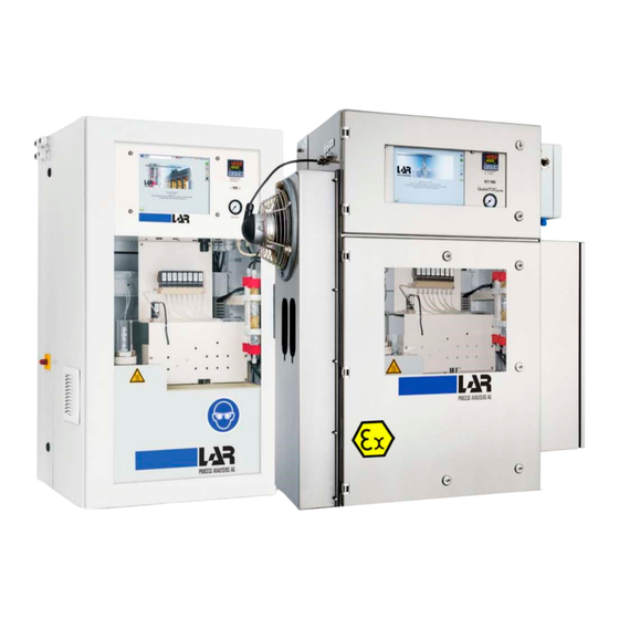
3 Product LAR | PROCESS ANALYSERS AG 3.1 Scope of Delivery Product This chapter gives an overview of the analyser and its components. Scope of Delivery ® The analyser „QuickTOC “for ATEX zone 2 , associated individual parts and any required operating purity material are delivered in a sturdy wooden crate. -
Page 28: Identification Plate
3 Product 3.2 Identification plate LAR | PROCESS ANALYSERS AG Identification plate On the side of the housing is a nameplate with name of the analyser, serial number, year built, mains voltage, power consumption, further technical data and the contact address of LAR Fig. -
Page 29: Construction Of The Analyser
3 Product LAR | PROCESS ANALYSERS AG 3.3 Construction of the Analyser Construction of the Analyser 3.3.1 Front View 1 Touchscreen 6 Valve block for samples 2 Temperature regulator (Actual/Target) 7 Calibration vessel 3 Pressure display of carrier gas prepressure 8 Sample vessel 4 Quartz wool filter 9 Injection block and furnace... - Page 30 3 Product 3.3 Construction of the Analyser LAR | PROCESS ANALYSERS AG Depending on the method of measurement and the number of samples, there is an additional cabinet on the right side of the analyser with pumps for transporting the samples to the analyser.
-
Page 31: Bottom Of The Analyser
3 Product LAR | PROCESS ANALYSERS AG 3.3 Construction of the Analyser 3.3.2 Bottom of the Analyser 1 Maintenance lid for reactor foot 6 Inlet for emergency cooling 2 Feedthrough for electric connection 7 Inlet for rinsing solution 3 Carrier gas inlet 8 Acid inlet 4 Incoming signals (from relays) 9 Sample drain... -
Page 32: Right Side
3 Product 3.3 Construction of the Analyser LAR | PROCESS ANALYSERS AG 3.3.3 Right side 1 Carrier gas outlet 2 Carrier gas outlet 3 Sample cabinet (Multi-Stream-Option) Fig. 6: Right side of the analyser ® User Manual QuickTOC ATEX 2 04E3920 purity... -
Page 33: Left Side
3 Product LAR | PROCESS ANALYSERS AG 3.4 Components of the Analyser 3.3.4 Left side 1 Rinsing air inlet 3 Ground connection 2 Main switch 4 Connection for trackball Fig. 7: Left side of the analyser Components of the Analyser To provide you with an overview of the components fitted, this section explains the most important com- ponents, and their positions and functions in the analyser. -
Page 34: Tube Cassette Pump
3 Product 3.4 Components of the Analyser LAR | PROCESS ANALYSERS AG 3.4.1.1 Tube Cassette Pump The tube cassette pump (Fig. 8) is used for different applications within the analyser and depends on the selected measurement method. Fig. 8: Tube cassette pump with five tube cassettes Danger of crushing During operation, the rollers of the tube cassette pump are in motion. -
Page 35: Sample Pump
3 Product LAR | PROCESS ANALYSERS AG 3.4 Components of the Analyser 3.4.1.3 Sample Pump The sample pump (Fig. 10) is used to transport the sample(s) for the TOC-difference and TConly meth- ods. The number of sample pumps depends on the number of sample streams. Fig. -
Page 36: Glass Components
3 Product 3.4 Components of the Analyser LAR | PROCESS ANALYSERS AG 3.4.2 Glass Components The following glass components are installed in the analyser. The number of glass components can vary depending on the number of sample streams and the measurement method 3.4.2.1 Calibration vessel The calibration vessel (1) is located in the main cabinet. -
Page 37: Sample Vessels
3 Product LAR | PROCESS ANALYSERS AG 3.4 Components of the Analyser 3.4.2.2 Sample Vessels The sample vessels (2) with the corresponding sample pumps (3) are located in the add-on unit. Fig. 12: Sample vessels in the add-on unit ® 04E3920 User Manual QuickTOC ATEX 2... -
Page 38: Ceramic Furnace
3 Product 3.4 Components of the Analyser LAR | PROCESS ANALYSERS AG 3.4.3 Ceramic Furnace The catalyst-free ceramic furnace is the heart of the analyser. In it, all carbon compounds are reliably oxidised at 1,200°C, enabling a complete analysis of the sample. Absolute safety is guaranteed in every environment despite the high temperatures. - Page 39 3 Product LAR | PROCESS ANALYSERS AG 3.4 Components of the Analyser 1 Ceramic reactor pipe 2 Furnace 3 Thermocouple Fig. 14: Ceramic Furnace Fig. 15: Reactor foot ® 04E3920 User Manual QuickTOC ATEX 2 purity...
-
Page 40: Trackball
3 Product 3.5 Trackball LAR | PROCESS ANALYSERS AG Trackball The analyser can optionally be equipped with an external trackball. With the external trackball, you can control the analyser and operate the keyboard on the screen without having to open the case. This pre- vents the overpressure in the analyser from being reduced or having to rebuild first. - Page 41 3 Product LAR | PROCESS ANALYSERS AG 3.6 Components of the Explosion Protection gas. Only after successful rinsing is the analyser (3) switched on and the interfaces connected to the custo- mer level. An error is output at a relay output of the control unit as "Alarm". For service work on the device by trained personnel there is a bypass mode in the control unit, which is protected by a password Fig.
-
Page 42: Cooling And Emergency Cooling
3 Product 3.6 Components of the Explosion Protection LAR | PROCESS ANALYSERS AG 3.6.2 Cooling and Emergency Cooling The analyser is equipped with a heatpipe (3) in order to keep the inner temperature of the casing within acceptable limits for the control logic - despite the high temperature of the furnace. Deflectors (4) within the heatpipe transport the hot air out of the casing. - Page 43 3 Product LAR | PROCESS ANALYSERS AG 3.6 Components of the Explosion Protection Fig. 21: Heatpipe, inside view Depending on the temperature class, the cooling is equipped with a corresponding fan. • The fan (7) (similar to illustration) complies with the specifications for temperature class T4. •...
- Page 44 3 Product 3.6 Components of the Explosion Protection LAR | PROCESS ANALYSERS AG Fig. 23: Furnace tubing for cooling and emegency cooling ® User Manual QuickTOC ATEX 2 04E3920 purity...
-
Page 45: Connections
3 Product LAR | PROCESS ANALYSERS AG 3.6 Components of the Explosion Protection 3.6.3 Connections Danger of burns During operation, the furnace is extremely hot. Use heat-proof gloves when working on the furnace system. Danger The analyser has various connectors, which are detailed in the following chapter. ®... -
Page 46: Mounting Plate
3 Product 3.6 Components of the Explosion Protection LAR | PROCESS ANALYSERS AG 3.6.3.1 Mounting Plate The device comes without power cord. The power cord must be supplied by the end- user. Notice ® User Manual QuickTOC ATEX 2 04E3920 purity... - Page 47 3 Product LAR | PROCESS ANALYSERS AG 3.6 Components of the Explosion Protection 1 TRC-Board (RS232 Serial Interface, Relays, 10 Connection Terminal for Ambient Air Digital Inputs) Preparation Unit (24 V/DC) 2 Switching power supply(24 V / 13 A) 11 Connection Terminals for Analog Outputs 3 Relaiys for sample pump (X101) 4 Switching power supply 12 V...
-
Page 48: Power Supply
3 Product 3.6 Components of the Explosion Protection LAR | PROCESS ANALYSERS AG 3.6.3.2 Power Supply PE (green): Protective conductor N (blue): Neutral L (gray): Conductor Fig. 25: Connection to power supply Warning of improper electrical connection The analyser may be damaged if it is connected to a local power supply not specified on the type plate. -
Page 49: Electronic Connections (Digital And Analog Connections)
3 Product LAR | PROCESS ANALYSERS AG 3.6 Components of the Explosion Protection 3.6.4 Electronic Connections (Digital and Analog Connections) De-energize the analyser before beginning to cabling the system. Notice 3.6.4.1 Connections on the TRC-Board The analyser is equipped with a TRC board for connection to external devices or to a process control system. - Page 50 3 Product 3.6 Components of the Explosion Protection LAR | PROCESS ANALYSERS AG Fig. 27: TRC-Board (RS 232 serial interface, digital inputs relays) ® User Manual QuickTOC ATEX 2 04E3920 purity...
-
Page 51: Rs232 Serial Interface
3 Product LAR | PROCESS ANALYSERS AG 3.6 Components of the Explosion Protection 3.6.4.2 RS232 Serial Interface The serial RS232 interface can be used to transfer the current data to a remote computer unit that is connected to the analyser via an RS232 cable. The pin assignment of the interface is shown in Fig. 27, page 42. -
Page 52: Relays
3 Product 3.6 Components of the Explosion Protection LAR | PROCESS ANALYSERS AG 3.6.4.4 Relays The analyser has 8 isolated relays (switch contacts). These are capable of switching external circuits up to 24 V DC / AC with 1 A and can be assigned by the user in the operating software. The relays can be programmed as normally open and normally closed (settings in the software, default is normally open). - Page 53 3 Product LAR | PROCESS ANALYSERS AG 3.6 Components of the Explosion Protection Power supply Set Analog Outputs Pressostat Water Alarm Analog outputs 0/4-20 mA max. load 500 W Sample stream1 Fig. 29: Terminal plan (part I) - Power supply, fixed analogue outputs, programmable analogue out- puts ®...
- Page 54 3 Product 3.6 Components of the Explosion Protection LAR | PROCESS ANALYSERS AG Sample stream easured value Sample stream 2 Sample stream 3 Fig. 30: Terminal plan (part II) - Programmable analogue outputs ® User Manual QuickTOC ATEX 2 04E3920 purity...
- Page 55 3 Product LAR | PROCESS ANALYSERS AG 3.6 Components of the Explosion Protection Sample stream 4 Sample stream 5 Sample stream 6 Fig. 31: Terminal plan (part III) - Programmable analogue outputs ® 04E3920 User Manual QuickTOC ATEX 2 purity...
-
Page 56: Carrier Gas
3 Product 3.6 Components of the Explosion Protection LAR | PROCESS ANALYSERS AG 3.6.5 Carrier Gas The carrier gas supplied to the measuring system must be CO2-free, as it carries the CO2 produced du- ring the oxidation of the sample to the detector. The carrier gas must be supplied with a pre-pressure of 3.5 to 4 bar. -
Page 57: Installation
4 Installation LAR | PROCESS ANALYSERS AG 4.1 Installation Procedure Installation The following chapter will give you instructions for installing the analyser. The following installation pro- cedure serves as overview. Perform the installation correctly and log the installation process that you should perform and log correctly. -
Page 58: Site Selection - Ambient Conditions
4 Installation 4.2 Site Selection - Ambient Conditions LAR | PROCESS ANALYSERS AG Tabelle 5: Installation protocol for the analyser Task Criteria Comment • Dry and frost-proof • Temperature: 5 -35° C Ensure Environment • Rel. humidity: < 80% Conditions •... - Page 59 4 Installation LAR | PROCESS ANALYSERS AG 4.2 Site Selection - Ambient Conditions Warning of incorrect electric connections The analyser may be damaged if it is not connected to the mains matching the data stated on the nameplate. Warning Before the analyser is switched on, a check must be run on whether the local voltage supply matches that on the nameplate.
-
Page 60: Mounting The Analyser On-Site
4 Installation 4.3 Mounting the Analyser On-Site LAR | PROCESS ANALYSERS AG Mounting the Analyser On-Site The analyser is normally mounted on to a wall (Chapter 4.3.2 from page 54) or to the LAR mounting rack (Chapter 9.2 on page 156). -
Page 61: Maximum Swing-Open Of The Analyser
4 Installation LAR | PROCESS ANALYSERS AG 4.3 Mounting the Analyser On-Site 4.3.1 Maximum Swing-Open of the Analyser For all mounting options, distance to side and opposite walls must be maintained so that the analyser can be swung open. Notice 1 Rear housing 2 Front housing 3 Housing door... -
Page 62: Wall Mounting
4 Installation 4.3 Mounting the Analyser On-Site LAR | PROCESS ANALYSERS AG 4.3.2 Wall Mounting Observe the following mounting dimensions: Minimum 1.430 x 1.760 x 1.210 mm (W x H x D) M1 - M4: Mounting points for analyser Q1 - Q2: Mounting points for carrier gas conditioning ®... -
Page 63: Carrier Gas
4 Installation LAR | PROCESS ANALYSERS AG 4.4 Carrier Gas Fig. 35: Wall mounting of the analyser Improper Mounting! The distance to side and opposing walls must be kept so that the analyser can be ope- ned. Take into account the condition of the wall to which the analyser is to be affixed. The Warning wall should have the solidity of a concrete wall. -
Page 64: Sample Inlet And Drain
4 Installation 4.5 Sample Inlet and Drain LAR | PROCESS ANALYSERS AG • dew point: max. -5°C • provided in the direct vicinity of the analyser Sample Inlet and Drain Please ensure that sample inlet and drain are depressurised and available in the direct vicinity of the analyser. -
Page 65: Signal Connections
4 Installation LAR | PROCESS ANALYSERS AG 4.7 Signal connections It is possible to use other mains voltages. If you have any question, please contact your local partner or the Technical Support of LAR (Chapter 15 on page 245). Notice Signal connections The analyser has different digital connections. -
Page 66: Provide Acid Solution (Toc-Direct And Toc-Difference Method)
4 Installation 4.9 Provide Acid Solution (TOC-Direct and TOC-Difference Method) LAR | PROCESS ANALYSERS AG See Chapter 6.1.2 on page 55. Provide Acid Solution (TOC-Direct and TOC-Difference Method) For the usage of the analyser with the TOC-Direct or TOC-Difference Method, an acid solution for strip- ping out inorganic carbon compounds (TIC) must be provided. -
Page 67: Provide Calibration Standards
4 Installation LAR | PROCESS ANALYSERS AG 4.10 Provide Calibration Standards 4.10 Provide Calibration Standards A calibration standard must be provided by the operator to calibrate the analyser. See Chapter 6.2 from page 57. Warning of improper storage The calibration standard must be stored in a cool place (such as a refigerator). For the start-up, please use a calibration standard not older than five days. - Page 68 4 Installation 4.10 Provide Calibration Standards LAR | PROCESS ANALYSERS AG ® User Manual QuickTOC ATEX 2 04E3920 purity...
-
Page 69: Start-Up
5 Start-up LAR | PROCESS ANALYSERS AG 5.1 Procedure Start-up This section provides all information about the start-up of the analyser. The following start-up procedure serves as an overview. The start-up must be carried out properly and documented by Technical Support of LAR or by another person authorised by LAR. -
Page 70: Checking The Pre-Fusing
5 Start-up 5.2 Checking the Pre-Fusing LAR | PROCESS ANALYSERS AG Task Criteria Comment • Fuse Lock is removed Switching on the fuses • All Fuses are switched on Filling and installing the • Reactor Pipe is filled reactor pipe •... -
Page 71: Removing Transport Locks
5 Start-up LAR | PROCESS ANALYSERS AG 5.4 Removing Transport Locks Removing Transport Locks Transport locks are affixed to safeguard the analyser and its components during transport. They must be removed before the analyser is used. ® 04E3920 User Manual QuickTOC ATEX 2 purity... -
Page 72: Furnace Transport Screw
5 Start-up 5.4 Removing Transport Locks LAR | PROCESS ANALYSERS AG 5.4.1 Furnace Transport Screw Transport locks can also be affixed to accessories and options. Information to remove transportation locks of accessories and options can be found in Chapter 9 from page 169. Notice For transportation, the furnace is secured with a bolt and a spacer sleeve, which must be removed for operation. -
Page 73: Aligning The Voltage
5 Start-up LAR | PROCESS ANALYSERS AG 5.5 Aligning the Voltage Aligning the Voltage Check the power supply. Compare the mains voltage with that specified on the analyser (siehe Fig. 3, page 20) ab. Switching on the Pre-Fusing In order to switch the analyser on, the lock on the automatic circuit breaker must be removed and the fuses must be switched on. - Page 74 5 Start-up 5.7 Filling and Installing the Reactor PipeReactor Pipe LAR | PROCESS ANALYSERS AG Remove the following components from the packaging: • Reactor Pipe • Protective Pipe • Ceramic Sieve • Ceramic Balls • Green Protective Seal Assembly of the Reactor Pipe: Fig.
- Page 75 5 Start-up LAR | PROCESS ANALYSERS AG 5.7 Filling and Installing the Reactor PipeReactor Pipe Damage due to improper filling Incorrect filling of the reactor pipe can damage the reactor pipe. Use a funnel to fill the ceramic balls so that the ceramic balls do not fall between the Warning reactor pipe and the protective pipe.
-
Page 76: Completing The Furnace
5 Start-up 5.8 Completing the Furnace LAR | PROCESS ANALYSERS AG Completing the Furnace Install the furnace system as shown in Fig. 40, page 68 and Fig. 41, page 69. Fig. 40: Assembly of the reactor head ® User Manual QuickTOC ATEX 2 04E3920 purity... - Page 77 5 Start-up LAR | PROCESS ANALYSERS AG 5.8 Completing the Furnace Fig. 41: Assembly of the reactor foot Mount the reactor foot when the furnace has reached a temperature of approx. 800° C. The high temperature simplifies the assembly of the reactor bottom. Notice ®...
-
Page 78: Installation Of The Pump Tubes
5 Start-up 5.9 Installation of the Pump Tubes LAR | PROCESS ANALYSERS AG Installation of the Pump Tubes 5.9.1 Installation of the Tubes into the Tube Cassette Pump In order to pump the solutions, the tubes must be placed into the tube cassette pump correctly. Proceed as follows: Use the overview to localise all tube cassette pumps (Tab. - Page 79 5 Start-up LAR | PROCESS ANALYSERS AG 5.9 Installation of the Pump Tubes Proceed as follows: Locate all sample pumps by using Tab. 2, page 24. Open the upper lid (1) of the sample pump. Place the tube (2) close to the roller (3). Pay attention not to twist the tube (2).
-
Page 80: Analyser Tubing
5 Start-up 5.10 Analyser Tubing LAR | PROCESS ANALYSERS AG 5.10 Analyser Tubing Inside the analyser, samples, reagents and the carrier gas are transported from one component to the next. Different tubes are used for this, which must be connected properly to the components. For tubing of your analyser, follow the flow diagram for your configuration (Chapter 12 from page 217). -
Page 81: Connecting The Control Unit
5 Start-up LAR | PROCESS ANALYSERS AG 5.11 Connecting the Control Unit 5.11 Connecting the Control Unit Connect the F840 control unit according to the following connection diagram. Fig. 47: Electric connection for the control unit ® 04E3920 User Manual QuickTOC ATEX 2 purity... -
Page 82: Connecting The Furnace Emergency Cooling
5 Start-up 5.12 Connecting the Furnace Emergency Cooling LAR | PROCESS ANALYSERS AG 5.12 Connecting the Furnace Emergency Cooling Connect the furnace emergency cooling. Fig. 48: Connection of the furnace emergency cooling 5.13 Switch on the Analyser The analyser is switched on for the first time by Technical Support of LAR or by a person authorised by LAR. -
Page 83: Setting The Bypass For The Control Unit
5 Start-up LAR | PROCESS ANALYSERS AG 5.14 Setting the Bypass for the Control Unit The control unit produces an overpressure of 7 to 10 mbar in the analyser for 10 to 15 minutes to check the tightness of the pressurized enclosure. After successful verification of the tightness, the overpressure in the analyser is reduced to 2 to 3 mbar. -
Page 84: Rinse The Injection System Und Sample Tubes
5 Start-up 5.15 Rinse the Injection System und Sample Tubes LAR | PROCESS ANALYSERS AG 5.15 Rinse the Injection System und Sample Tubes Before the first measurement, the injection system and sample tubes must be rinsed. Notice Proceed as follows: Switch to the “Service Action”... -
Page 85: Operation With Trackball
5 Start-up LAR | PROCESS ANALYSERS AG 5.19 Operation with Trackball 5.19 Operation with Trackball See Chapter 9.3 on page 158. 5.20 Start Measuring Mode Before the measuring mode is started, the control unit produces the pressurized enclosure. Close the analyser. The control unit produces an overpressure of 7 to 10 mbar in the analyser for 10 to 15 minutes to check the tightness of the pressurized enclosure. - Page 86 5 Start-up 5.20 Start Measuring Mode LAR | PROCESS ANALYSERS AG ® User Manual QuickTOC ATEX 2 04E3920 purity...
-
Page 87: Reagents And Calibration Standards
6 Reagents and Calibration Standards LAR | PROCESS ANALYSERS AG 6.1 Reagents Reagents and Calibration Standards Deionised water, rinsing water, calibration standards (and possibly acid solutions) are required for the analyser measurement mode. This section shows how you can prepare the calibration standards and solutions yourself. -
Page 88: Phosphoric Acid (H3Po4) For Toc-Difference Method
6 Reagents and Calibration Standards 6.1 Reagents LAR | PROCESS ANALYSERS AG Proceed as follows: Fill a 5 l graduated flask with 5 litres of deionised water. Add 1 ml of 85% phosphoric acid (H Degas the rinsing water using underpressure or put it into an ultrasonic bath for five minutes. Keep the rinsing water underneath the analyser (e.g. -
Page 89: Other Chemicals
6 Reagents and Calibration Standards LAR | PROCESS ANALYSERS AG 6.1 Reagents 6.1.5 Other Chemicals If ambient air is cleaned with LAR equipment as a carrier gas, the following chemicals are required: • Activated carbon (1) (instrument air / zero air generator supply only) •... -
Page 90: Stock Solution - Toc-Difference Method
6 Reagents and Calibration Standards 6.1 Reagents LAR | PROCESS ANALYSERS AG 6.1.6.1 Stock Solution - TOC-Difference Method This section shows how to prepare a stock solution for TOC-Difference Method analogous to DIN EN 1484:1987. Chemicals required • 6.382 g Potassium hydrogen phthalate (C ) p.a. -
Page 91: Dilution Of The Stock Solution - Toc-Difference Method
6 Reagents and Calibration Standards LAR | PROCESS ANALYSERS AG 6.1 Reagents 6.1.6.2 Dilution of the Stock Solution - TOC-Difference Method Because the analysers work in different working ranges, the following three stock solution dilutions are listed. These dilutions enable calibration standards to be made which have a lower concentration than listed in the table below. -
Page 92: Calibration Standards - Toc-Direct Method / Tconly Method
6 Reagents and Calibration Standards 6.1 Reagents LAR | PROCESS ANALYSERS AG 6.1.7 Calibration Standards - TOC-Direct Method / TConly Method This section explains how you can prepare the calibration standards for the TOC-Direct Method and TConly Method yourself. First, a stock solution needs to be prepared which can then be diluted to arrive at the calibration standard concentration required. -
Page 93: Dilution Of The Stock Solution - Toc-Direct Method / Tconly Method
6 Reagents and Calibration Standards LAR | PROCESS ANALYSERS AG 6.1 Reagents 6.1.7.2 Dilution of the Stock Solution - TOC-Direct Method / TConly Method Because the analysers work in different working ranges, the following four stock solution dilutions are listed. These dilutions enable calibration standards to be made which have a lower concentration than listed in the table below. - Page 94 6 Reagents and Calibration Standards 6.1 Reagents LAR | PROCESS ANALYSERS AG ® User Manual QuickTOC ATEX 2 04E3920 purity...
-
Page 95: How To Work With The Analyser
7 How to Work With the Analyser LAR | PROCESS ANALYSERS AG How to Work With the Analyser Once all installation and commissioning points have been met, the main switch (1) on the left side of the analyser can be operated by an authorized LAR technician to "ON". Fig. - Page 96 7 How to Work With the Analyser LAR | PROCESS ANALYSERS AG After a self-test of the device, the login screen is displayed. Enter your login details here to log in. To get to user level I for the first time, press the button at the bottom right (1) without entering the password.
-
Page 97: General
7 How to Work With the Analyser LAR | PROCESS ANALYSERS AG 7.1 General The analyser can only start a measurement when the furnace has reached the wor- king temperature. Notice General ® The QuickTOC is equipped with a touchscreen. Use your fingers or a stylus to operate the touch- purity screen Damage to the touchscreen... -
Page 98: Configuration
7 How to Work With the Analyser 7.2 Configuration LAR | PROCESS ANALYSERS AG • User level 2 The user can view data (such as readings) and use functions described in this chapter. For user level 2 an access authorization with password can be set up (Chapter 7.3.1 on page 120). Fig. -
Page 99: Setting The Measuremement Parameters
7 How to Work With the Analyser LAR | PROCESS ANALYSERS AG 7.2 Configuration Some values are set up by LAR Technical Support or a LAR-authorised technician. All values depend on the application and must be adapted to it. To change the values of the operating parameters, please contact LAR Technical Support Notice 7.2.2... -
Page 100: Measuring Intervals Of The Sample Streams 1 To 6
7 How to Work With the Analyser 7.2 Configuration LAR | PROCESS ANALYSERS AG 7.2.2.1 Measuring intervals of the sample streams 1 to 6 Here, the measurement intervals of the measurements per sample stream are selected. If a measure- ment takes more time than the selected interval, the instrument will automatically select the next higher interval. -
Page 101: Filling Time Of The Injection Loop
7 How to Work With the Analyser LAR | PROCESS ANALYSERS AG 7.2 Configuration 7.2.2.9 Filling time of the injection loop Here you can specify the duration in which the device fills the injection loop with sample. 7.2.2.10 Waiting time of the injection loop Here you can specify how long the filled injection loop will wait for the sample to be injected into the oven. -
Page 102: Setting Parameters For Gas Measuremement
7 How to Work With the Analyser 7.2 Configuration LAR | PROCESS ANALYSERS AG 7.2.3 Setting Parameters for Gas Measuremement The following parameters can be set in user level 2 for a gas measurement (gas calibration / gas valida- tion): Fig. -
Page 103: Injection Time Carrier Gas
7 How to Work With the Analyser LAR | PROCESS ANALYSERS AG 7.2 Configuration 7.2.3.7 Injection time carrier gas Here, the duration can be specified in which the device is to inject the carrier gas from the injection loop into the oven. A zero-point measurement is performed. 7.2.4 Calibration In user level 2 you can start a manual calibration. -
Page 104: Perform A 1-Point Calibration For A Sample Stream
7 How to Work With the Analyser 7.2 Configuration LAR | PROCESS ANALYSERS AG Save button Fig. 57: Perform Calibration Screen (Example) In this screen, a one-point calibration or a multi-point calibration for a stream can be performed. For a multi-point calibration, it must be noted that the calibration solutions can only be measured one after the other. -
Page 105: Perform A Multipoint Calibration (Three Solutions) For A Sample Stream
7 How to Work With the Analyser LAR | PROCESS ANALYSERS AG 7.2 Configuration previous graph. 11. In the Calibration Results screen, the calibration results (slope and intercept) can be viewed and activated. 7.2.4.1.2 Perform a multipoint calibration (three solutions) for a sample stream Preparation of the calibration solutions and positioning of the first calibration vessel. -
Page 106: Calibration Results
7 How to Work With the Analyser 7.2 Configuration LAR | PROCESS ANALYSERS AG Back to Start of Calibration Fig. 59: Calibrate Screen - Show Details (Example) Back to Start of Calibration Fig. 60: Calibrate Screen - Calibration Graph (Example) 7.2.4.2 Calibration Results After a successful calibration (Chapter 7.2.4.1 from page 95), the results are displayed on the "Calibra-... -
Page 107: Injection Volume
7 How to Work With the Analyser LAR | PROCESS ANALYSERS AG 7.2 Configuration Fig. 61: Screen with Calibration results 7.2.5 Injection Volume In user level 2, the injection volumes injected into the furnace during the measurement can be determi- ned: •... -
Page 108: Volume Of The Injection Loop
7 How to Work With the Analyser 7.2 Configuration LAR | PROCESS ANALYSERS AG 7.2.5.1 Volume of the Injection Loop Here you can view the volume of the injection loop. For the measuring methods TConly or TOC Difference, the injection volume should be at least 800 μl (1200 μl), otherwise condensate will be formed in the reactor bottom and CO2 will be absorbed. -
Page 109: Testing The Relays
7 How to Work With the Analyser LAR | PROCESS ANALYSERS AG 7.2 Configuration The! Operator is used to invert a condition (! L1 means that the condition is met if the set limit no. 1 has NOT been exceeded). •... - Page 110 7 How to Work With the Analyser 7.2 Configuration LAR | PROCESS ANALYSERS AG Fig. 64: PC settings screen Change password For user level II, a password can be set up. If the password is deactivated, you need the USB key with the access permissions.
-
Page 111: Channel Display
7 How to Work With the Analyser LAR | PROCESS ANALYSERS AG 7.2 Configuration After pressing all nine calibration points, the view returns to the PC Settings screen. Coordinates Fig. 65: Calibrate touchscreen 7.2.8 Channel Display In the "Channel display" view, the measured value displays can be defined. A channel is defined by sam- ple flow, sensor, function, parameters and channel parameters. -
Page 112: Measured Values Screen
7 How to Work With the Analyser 7.2 Configuration LAR | PROCESS ANALYSERS AG 7.2.9 Measured Values Screen The measured value screen displays the current measured values and the time they were measured. To change the settings, please contact LAR technical support (Chapter 15.1 on page 183) Fig. -
Page 113: Signal Curve
7 How to Work With the Analyser LAR | PROCESS ANALYSERS AG 7.2 Configuration 7.2.10 Signal Curve To view the measurement curve, go to the "Signal Curve" view in Level II. If the analyser has more than one sensor, the detector can be selected on the upper left side of the screen. Fig. -
Page 114: Service Actions
7 How to Work With the Analyser 7.2 Configuration LAR | PROCESS ANALYSERS AG The zero signal of the detector is measured during an adjustable period of time before the start of the measurement. Upon detection of the zero or zero signal, the measurement begins when the difference between the current signal and the zero signal is greater than the value of the start integration. -
Page 115: Select Sample Flow For Flushing The Sample Tubes
7 How to Work With the Analyser LAR | PROCESS ANALYSERS AG 7.2 Configuration Fig. 70: Service actions The sample pumps must not be in continuous operation, as otherwise warranty claims for the pumps may go out. If a new measurement, calibration or individual measurement is to be carried out again after a care or maintenance operation by pressing the "Perform maintenance"... -
Page 116: Maintenance
7 How to Work With the Analyser 7.2 Configuration LAR | PROCESS ANALYSERS AG Fig. 71: Service actions - „Perform maintenance“ The icon (1) in the status bar on the right symbolizes that the "Perform maintenance" button has been pressed. 7.2.12.2 Maintenance Pressing the „End Maintenance“... -
Page 117: Switching The Condensate Pump On And Off
7 How to Work With the Analyser LAR | PROCESS ANALYSERS AG 7.2 Configuration The heating time of the oven is about 120 minutes (2 hours). This corresponds to a heating rate of 10° C / min. This time is fixed and not changeable. Notice 7.2.12.5 Switching the Condensate Pump On and Off Press the "End maintenance"... -
Page 118: Auto Check
7 How to Work With the Analyser 7.2 Configuration LAR | PROCESS ANALYSERS AG and CV) can be adjusted before a single measurement. Once the three parameters (repeated measure- ments, outliers, max.CV) have been set and saved with the disk symbol, the single measurement can be started via the "Start single measurement"... - Page 119 7 How to Work With the Analyser LAR | PROCESS ANALYSERS AG 7.2 Configuration Fig. 73: „Auto Check“ screen (Example for 3 sample streams) Fig. 74: „Auto Check“ screen - Activation of one sample stream (Example) ® 04E3920 User Manual QuickTOC ATEX 2 purity...
-
Page 120: Auto Calibration: Automatic Calibration Through Calibration Standards
7 How to Work With the Analyser 7.2 Configuration LAR | PROCESS ANALYSERS AG 7.2.14.1 Auto Calibration: Automatic Calibration through Calibration Standards This feature allows automatic calibration of the instrument, where each sample stream can be selected and eight different time intervals are available. In the input field "Deviation", the percentage deviation of the new calibration must be entered. -
Page 121: Rinse Sample Tubes
7 How to Work With the Analyser LAR | PROCESS ANALYSERS AG 7.2 Configuration the channel by pressing the corresponding selection button. To enter the minimum or maximum limit and name, click in the white input field under "Minimum / Maximum". A number field and a keyboard are dis- played. -
Page 122: Rinse Before Measurement
7 How to Work With the Analyser 7.2 Configuration LAR | PROCESS ANALYSERS AG 7.2.16.1 Rinse before Measurement Here you can set whether the tubing system should be rinsed before a measurement with rinse water via Y3Y10. 7.2.16.2 Purge Time If the parameter "Rinse before measurement"... - Page 123 7 How to Work With the Analyser LAR | PROCESS ANALYSERS AG 7.2 Configuration 1 Overview of the database 2 Data in table form 3 Dayly results 4 Save data to storage device 5 Save all data to storage device 6 Dub parameters Fig.
-
Page 124: Data In Table Form
7 How to Work With the Analyser 7.2 Configuration LAR | PROCESS ANALYSERS AG The existing data and settings will be overwritten, please contact the technical support of the LAR (chapter 15.1 from page 203)! Notice 7.2.17.1 Data in Table Form The measured values are displayed to the right of the timestamp when you press the "Data in table form"... -
Page 125: Log
7 How to Work With the Analyser LAR | PROCESS ANALYSERS AG 7.2 Configuration Fig. 79: Database - curve form (Example) 7.2.18 The logbook screen is only displayed from user level 2 onwards. Notice The logbook can be accessed via the status bar. To do this, press the icon "To get to the logbook"... - Page 126 7 How to Work With the Analyser 7.2 Configuration LAR | PROCESS ANALYSERS AG The list contains limit values or overshoots with times. To see the subfolders, press the small triangle on the left of Errors, System, Limit or Service Log. A corresponding listing is displayed. 1 View of the log 2 Go to Log 3 Unsolved errors...
-
Page 127: Saving Data
7 How to Work With the Analyser LAR | PROCESS ANALYSERS AG 7.2 Configuration Fig. 82: Database screen - Log - View of actual errors 7.2.19 Saving Data Data storage takes place during commissioning and maintenance of the device. Current operating pa- rameters are stored and archived in the LAR database. -
Page 128: Good To Know
7 How to Work With the Analyser 7.3 Good to know LAR | PROCESS ANALYSERS AG Only an authorized technician should perform an analog output calibration, as this requires opening the rear housing. Open the rear part of the unit. Connect the multimeter (amperemeter) to the analogue output. -
Page 129: Furnace On - Off
7 How to Work With the Analyser LAR | PROCESS ANALYSERS AG 7.3 Good to know 7.3.4 Furnace On - Off Manually switching the furnace on - off Please switch off the oven for maintenance purposes only. This can be done in the "Service Actions" view (Fig. -
Page 130: User Level 3
7 How to Work With the Analyser 7.3 Good to know LAR | PROCESS ANALYSERS AG Fig. 84: Save - first step Fig. 85: Save - second step In the second step of saving two values can be seen in the screen mask. The first va- lue is the previous parameter value and the second value is the desired new parame- ter value that has been entered. -
Page 131: Calibration Results
7 How to Work With the Analyser LAR | PROCESS ANALYSERS AG 7.3 Good to know Activate / deactivate password protection for user level 2 As a user with authorization for user level 3, you can activate or deactivate password protection in user level 2. -
Page 132: Hardware Info
7 How to Work With the Analyser 7.3 Good to know LAR | PROCESS ANALYSERS AG The device has a so-called CAN circuit diagram. In the CAN circuit diagram, all parts of the device are entered with their own ID. The device independently tests this plan and displays the results in this screen. -
Page 133: Digital Out 1, 2 And 3
7 How to Work With the Analyser LAR | PROCESS ANALYSERS AG 7.3 Good to know Fig. 91: DIGITAL IN 2 screen Fig. 92: DIGITAL IN 3 screen 7.3.10.6 DIGITAL OUT 1, 2 and 3 These three screens show the status of digital outputs 1, 2 and 3. The values can be changed manually. ®... - Page 134 7 How to Work With the Analyser 7.3 Good to know LAR | PROCESS ANALYSERS AG Fig. 93: DIGITAL OUT 1 screen Fig. 94: DIGITAL OUT 2 screen Fig. 95: DIGITAL OUT 3 screen ® User Manual QuickTOC ATEX 2 04E3920 purity...
-
Page 135: Calibrations
7 How to Work With the Analyser LAR | PROCESS ANALYSERS AG 7.3 Good to know 7.3.11 Calibrations Calibrate in two different screens: • in user level 2 in the screen "Perform calibration" • in user level 3 in the screen "Service Calibration" Before calibration can be performed, the necessary calibration solution must be pro- vided and the necessary level II adjustments made in the Calibrate screen. - Page 136 7 How to Work With the Analyser 7.3 Good to know LAR | PROCESS ANALYSERS AG calibration solution. Enter the maximum CV in% for calibration in the Perform Calibration screen. After selecting the solution number, it will be displayed in user level 3 in the "Service Calibration" screen.
-
Page 137: Service Parameter
7 How to Work With the Analyser LAR | PROCESS ANALYSERS AG 7.3 Good to know 7.3.12 Service Parameter Fig. 97: Service Parameter screen Define and view parameters for the carrier gas flow in this screen. Definable parameter: • Also measure for gas flow errors (3) •... -
Page 138: Update Manager
7 How to Work With the Analyser 7.3 Good to know LAR | PROCESS ANALYSERS AG 7.3.13 Update Manager New start Fig. 98: Update Manager screen This screen allows new software updates to be installed. To do this, a USB stick with access authoriza- tion for user level 3 and the update must be connected to the device. -
Page 139: Names And Units
7 How to Work With the Analyser LAR | PROCESS ANALYSERS AG 7.3 Good to know 7.3.14 Names and Units Fig. 99: Names and Units screen In this screen, the parameter and channel settings can be viewed and a correlation factor adjusted for each channel. - Page 140 7 How to Work With the Analyser 7.3 Good to know LAR | PROCESS ANALYSERS AG Fig. 100: Control state screen To view the device status of the entire day (24-hour profile), go to the "Log" view and click on "Error" (Chapter 7.2.18 on page 117).
- Page 141 7 How to Work With the Analyser LAR | PROCESS ANALYSERS AG 7.3 Good to know Tabelle 14: Control State ® 04E3920 User Manual QuickTOC ATEX 2 purity...
- Page 142 7 How to Work With the Analyser 7.3 Good to know LAR | PROCESS ANALYSERS AG ® User Manual QuickTOC ATEX 2 04E3920 purity...
-
Page 143: Care And Maintenance
8 Care and Maintenance LAR | PROCESS ANALYSERS AG Care and Maintenance Only minor effort is required to service and maintain the analyser. This section shows you the best way to look after your analyser to guarantee trouble-free operation. The documentation of maintenance and service work is a precondition for any warranty and guarantee claims, and also represents a valuable aid in locating resolutions when malfunctions occur (Chapter 10 on page 163). -
Page 144: Overview Of Regular Care And Maintenance Actions
8 Care and Maintenance 8.1 Overview of Regular Care and Maintenance Actions LAR | PROCESS ANALYSERS AG Overview of Regular Care and Maintenance Actions The following maintenance schedule provides an overview of recommended and regular actions for ca- ring and maintaining your analyser. Visual inspections are used to check the applicative need for care and maintenance actions. -
Page 145: Protocol For Visual Inspection (Analyser)
8 Care and Maintenance LAR | PROCESS ANALYSERS AG 8.2 Protocol for Visual Inspection (Analyser) Protocol for Visual Inspection (Analyser) Visual Inspection Criteria Measures Interval: 1 week Check soda lime Zero signal • 0 - 0,1 FSR Contact support Carrier gas •... -
Page 146: Care And Maintenance Tasks
8 Care and Maintenance 8.3 Care and Maintenance Tasks LAR | PROCESS ANALYSERS AG If the signal is not within the permitted range, contact LAR Technical Support (chapter 11.1 on page 141). Check the carrier gas flow. The volume flow at the input vein should have values between 13.5 - 15.5 l / h. -
Page 147: Actions
8 Care and Maintenance LAR | PROCESS ANALYSERS AG 8.3 Care and Maintenance Tasks Interval Task Task Type Chapter 1 year Replace reactor tube or Maintenance Chapter 8.3.17 on change reactor filling (if page 147 necessary) Replace reactor seal (if Maintenance Chapter 8.3.18 from necessary) - Page 148 8 Care and Maintenance 8.3 Care and Maintenance Tasks LAR | PROCESS ANALYSERS AG Task Interval Measure Notes completed 3 months Check reactor pipe end and clean if necessary Inspection of the gas coo- ling pipes Check pump cassettes and ...
-
Page 149: Clean Vessel For Calibration Fluid And Replace Calibration Standard
8 Care and Maintenance LAR | PROCESS ANALYSERS AG 8.3 Care and Maintenance Tasks 8.3.3 Clean Vessel for Calibration Fluid and Replace Calibration Standard First stop measuring mode with the "Offline" button before carrying out this monitoring and maintenance activity. Notice Renew the calibration standard weekly (with automatic calibration!) to prevent a change in the standard. -
Page 150: Check The Gas Cooler
8 Care and Maintenance 8.3 Care and Maintenance Tasks LAR | PROCESS ANALYSERS AG screwdriver. Destruction of the reactor pipe filling Never insert the drill or screwdriver deeper than 7 cm into the reactor tube. Warning Fig. 101: Manual cleaning of the reactor pipe with a drill bit 8.3.8 Check the Gas Cooler The gas cooler is located in the lower part of the device behind the lower front panel. -
Page 151: Cleantube Cassette Pump And Pump Cassettes
8 Care and Maintenance LAR | PROCESS ANALYSERS AG 8.3 Care and Maintenance Tasks 1 Gas cooler 2 Tube connectors Fig. 102: Gas cooler, view from above 8.3.9 CleanTube Cassette Pump and Pump Cassettes Precondition: - Tube cassette pump and/or pump cassettes are contaminated. Take the pump cassettes from the pump. -
Page 152: Clean And Grease Bearing Pin
8 Care and Maintenance 8.3 Care and Maintenance Tasks LAR | PROCESS ANALYSERS AG Tube diameter Wall thick- ness Adjustment wheel Fig. 103: Sample pump Adjustment Reduced delivery rate of the pump Deviating settings can cause poor pump performance and incorrect results. Adjust the pump head according to the application and to the correct hose diameter. -
Page 153: Perform A Calibration
8 Care and Maintenance LAR | PROCESS ANALYSERS AG 8.3 Care and Maintenance Tasks be checked. Start the measurement to complete the check 8.3.13 Perform a calibration See Chapter 7.3.11 from page 127. 8.3.13.1 Perform a Gas Calibration Please check the stability of the carrier gas flow in the status screen. Make sure that the injection system of the injection loop has also been previously cleaned with calibration gas. -
Page 154: Check And Document The Status Of The Analyser
8 Care and Maintenance 8.3 Care and Maintenance Tasks LAR | PROCESS ANALYSERS AG Enter the gas calibration values in ppm in the far right box. Select the calibration points (at least three calibration points) and the number of injections for each calibration point.The different concentration results depend on the number of loop injections. -
Page 155: Replace Reactor Pipe Or Reactor Pipe Filling
8 Care and Maintenance LAR | PROCESS ANALYSERS AG 8.3 Care and Maintenance Tasks 8.3.17 Replace Reactor Pipe or Reactor Pipe Filling 1 Thermowell 2 Ceramic balls 3,5 - 4,5 mm 3 Ceramic balls 7 mm 4 Ceramic sieve Fig. 104: Reactor filling Danger of burns Allow the furnace to cool completely (2 hours in total). - Page 156 8 Care and Maintenance 8.3 Care and Maintenance Tasks LAR | PROCESS ANALYSERS AG Remove the furnace head and injection port from the reactor tube and set aside. 10. Make sure the furnace head, injection port, and reactor foot are removed. 11.
-
Page 157: Replace Reactor Seal
8 Care and Maintenance LAR | PROCESS ANALYSERS AG 8.3 Care and Maintenance Tasks The reactor tube filling shown in Abb. 104, Seite 147 is an excellent solution for the majority of applications. However, some applications can be optimized by varying the listed default fill. Any de- viations from the standard filling should be discussed in advance with LAR Technical Notice Support or with a LAR authorized service partner. - Page 158 8 Care and Maintenance 8.3 Care and Maintenance Tasks LAR | PROCESS ANALYSERS AG Fig. 105: Reactor foot with cooler Remove the two gaskets (1, Fig. 105, page 150) between the furnace base and heat sink. 10. Clean the base of ash and dirt with a damp cloth and insert two new gaskets. 11.
-
Page 159: Loop System Tube
8 Care and Maintenance LAR | PROCESS ANALYSERS AG 8.3 Care and Maintenance Tasks Fig. 107: Ractor pipe 20. Place the reactor tube (2) on a fireproof pad or place it with the taper down in a sand-filled bucket and allow to cool completely. 21. -
Page 160: Check Sample Drain Tubes And Replace
8 Care and Maintenance 8.3 Care and Maintenance Tasks LAR | PROCESS ANALYSERS AG 1 Solenoid valves 2 Loop tube 3 Connectors Fig. 108: Loop system 8.3.20 Check Sample Drain Tubes and Replace Check the sample drain tubes for brittleness and elasticity. If the tubes are brittle or inelastic, the hoses must be changed. -
Page 161: Replace Gas Filter
8 Care and Maintenance LAR | PROCESS ANALYSERS AG 8.3 Care and Maintenance Tasks After installing the freshly filled quartz wool filter, the status screen must be recalled. The pressure value [mbar] should not deviate too much from the previously read pressure value. 10. - Page 162 8 Care and Maintenance 8.3 Care and Maintenance Tasks LAR | PROCESS ANALYSERS AG ® User Manual QuickTOC ATEX 2 04E3920 purity...
-
Page 163: Accessories And Options
9 Accessories and Options LAR | PROCESS ANALYSERS AG 9.1 Overview Accessories and Options In this section you will find illustrations for and explanations of components you can select as accesso- ries or options for the analyser. Overview Accessories: • Mounting rack Options: •... -
Page 164: Mounting Rack
9 Accessories and Options 9.2 Mounting Rack LAR | PROCESS ANALYSERS AG Mounting Rack The analyser can be supplied with an optional LAR mounting rack. M1 - M4: Holes for the fixing of the Analyser Q1 - Q2: Holes for the fixing of the Ambient Air Preparation Unit / Reagent Cabinet Fig. - Page 165 9 Accessories and Options LAR | PROCESS ANALYSERS AG 9.2 Mounting Rack The following installation dimensions must be observed: min. 1,070 x 2,000 x 1,420 mm (W x H x D) The distance to side and opposing walls must be kept so that the analyser can be swi- velled open.
-
Page 166: Multi Parameter Option
9 Accessories and Options 9.3 Multi Parameter Option LAR | PROCESS ANALYSERS AG Multi Parameter Option The analyser may measure multiple parameters with single sample streams. This can be factory-set or be upgraded later. The analyser can be fitted with up to four detectors for this option. The parameters can also be set for every sample stream and channel. -
Page 167: Multi Stream Option
9 Accessories and Options LAR | PROCESS ANALYSERS AG 9.4 Multi Stream Option Multi Stream Option The analyser may measure up to six sample streams in succession. Each sample stream is equipped with a sample vessel and pump. The parallel switchover means that during the measurement cycle of one sample the preparation of the next sample starts thus there are no measurement delays. - Page 168 9 Accessories and Options 9.4 Multi Stream Option LAR | PROCESS ANALYSERS AG ® User Manual QuickTOC ATEX 2 04E3920 purity...
- Page 169 9 Accessories and Options LAR | PROCESS ANALYSERS AG 9.4 Multi Stream Option ® 04E3920 User Manual QuickTOC ATEX 2 purity...
- Page 170 9 Accessories and Options 9.4 Multi Stream Option LAR | PROCESS ANALYSERS AG ® User Manual QuickTOC ATEX 2 04E3920 purity...
-
Page 171: Minor Disruptions - Quickly Solved
10 Minor Disruptions - Quickly Solved LAR | PROCESS ANALYSERS AG 10.1 Preconditions for Fault-Free Measurement Mode Minor Disruptions - Quickly Solved 10.1 Preconditions for Fault-Free Measurement Mode If disruptions of your analyser occur during measurement mode and the causes are not entirely obvious, please check the following: Ambient conditions The ambient temperature must be within the range permitted. -
Page 172: Breakdowns
10 Minor Disruptions - Quickly Solved 10.2 Breakdowns LAR | PROCESS ANALYSERS AG 10.2 Breakdowns This section provides information on and solutions for possible malfunctions with the measurement system. Possible causes and actions are listed in the following table - the problem type is used as an indicator. -
Page 173: Check The Fuses - Automatic Circuit Breaker
10 Minor Disruptions - Quickly Solved LAR | PROCESS ANALYSERS AG 10.3 Check the Fuses - Automatic Circuit Breaker Table 16: Troubleshooting Problem Possible cause Actions Error E1810 is shown • Emergency shutdown of • Contact your local partner or the the furnace Technical Support of LAR •... -
Page 174: Breakdowns Of The Temperature Regulator
10 Minor Disruptions - Quickly Solved 10.4 Breakdowns of the Temperature Regulator LAR | PROCESS ANALYSERS AG 10.4 Breakdowns of the Temperature Regulator Your analyser is fitted with a high temperature furnace which facilitates conversion in full of the carbon contained in the sample to CO without catalysts. -
Page 175: Technical Data
11 Technical Data LAR | PROCESS ANALYSERS AG 11.1 Specifications Technical Data All graphic, electronic or mechanical changes intended for technical progress are re- served. Notice 11.1 Specifications Tabelle 19: Analyser specifications Type Dimensions/Description Housing Explosion protected housing, stainless steel (IP65), Certification ATEX EX II 3G Ex pz II T3 or EX II 3G Ex pz II T4 Type of explosion protection Overpressure encapsulation with rinse... -
Page 176: Ambient Conditions
11 Technical Data 11.2 Ambient Conditions LAR | PROCESS ANALYSERS AG 11.2 Ambient Conditions Tabelle 20: Ambient conditions Type Dimensions/Description Temperature min. 10°C - max. 42°C Humidity max. 80% Dimensions (wall mounting)) min. 1.030 x 1.760 x 1.210 mm (W x H x D) Dimensions ( mounting rack) min. -
Page 177: Flow Diagrams
LAR | PROCESS ANALYSERS AG 12 Flow Diagrams Flow Diagrams The analyser can be operated with different configurations and methods. Furthermore, several methods can be used in an analyser. If you have any questions, contact LAR Technical Support (Chapter 15.1 on page 183). -
Page 178: Tc-Only Method (1 Sample Stream)
12 Flow Diagrams 12.2 TC-Only Method (1 Sample Stream) LAR | PROCESS ANALYSERS AG 12.2 TC-Only Method (1 Sample Stream) Fig. 113: Flow diagram for TC-Only Method (1 Sample stream) ® User Manual QuickTOC ATEX 2 04E3920 purity... -
Page 179: Tc-Only Method (6 Sample Streams)
12 Flow Diagrams LAR | PROCESS ANALYSERS AG 12.3 TC-Only Method (6 Sample streams) 12.3 TC-Only Method (6 Sample streams) Fig. 114: Flow diagram for TOG-Difference Method (3 Sample streams) ® 04E3920 User Manual QuickTOC ATEX 2 purity... -
Page 180: Npoc Method (1 Sample Stream)
12 Flow Diagrams 12.4 NPOC Method (1 Sample stream) LAR | PROCESS ANALYSERS AG 12.4 NPOC Method (1 Sample stream) Fig. 115: Flow diagram for NPOC Method (1 Sample stream) ® User Manual QuickTOC ATEX 2 04E3920 purity... -
Page 181: Npoc Method (6 Sample Streams)
12 Flow Diagrams LAR | PROCESS ANALYSERS AG 12.5 NPOC Method (6 Sample streams) 12.5 NPOC Method (6 Sample streams) Fig. 116: Flow diagram for NPOC Method (6 Sample streams) ® 04E3920 User Manual QuickTOC ATEX 2 purity... - Page 182 12 Flow Diagrams 12.5 NPOC Method (6 Sample streams) LAR | PROCESS ANALYSERS AG ® User Manual QuickTOC ATEX 2 04E3920 purity...
-
Page 183: Logs And Protocols
13 Logs and Protocols LAR | PROCESS ANALYSERS AG Logs and Protocols On the following pages you will find the operating log and the protocols mentioned in the operating in- structions as a copy template. It is recommended that you make a few copies and file them in a folder at the end of the manual or separately. -
Page 184: Operating Log
13 Logs and Protocols 13.1 Operating Log LAR | PROCESS ANALYSERS AG 13.1 Operating Log ® User Manual QuickTOC ATEX 2 04E3920 purity... -
Page 185: Protocol For Visual Inspection (Analyser)
13 Logs and Protocols LAR | PROCESS ANALYSERS AG 13.2 Protocol for Visual Inspection (Analyser) 13.2 Protocol for Visual Inspection (Analyser) Visual Inspection Criteria Measures Interval: 1 week Zero signal • 0 - 0,1 FSR Check soda lime ... -
Page 186: Care Protocol (Analyser)
13 Logs and Protocols 13.3 Care Protocol (Analyser) LAR | PROCESS ANALYSERS AG 13.3 Care Protocol (Analyser) Task Interval Measure Notes completed 1 week Clean vessel for calibration fluid and replace calibration standard Check pump tubes and clean if ... -
Page 187: Maintenance Protocol (Analyser)
13 Logs and Protocols LAR | PROCESS ANALYSERS AG 13.4 Maintenance protocol (Analyser) 13.4 Maintenance protocol (Analyser) Task Interval Measure Notes completed 3 months Clean and grease bearing pin 6 months Replace pump tubes and conden- sate tubes 1 year Replace reactor tube or change ... -
Page 188: Functional Test Protocol (Analyser)
13 Logs and Protocols 13.5 Functional Test Protocol (Analyser) LAR | PROCESS ANALYSERS AG 13.5 Functional Test Protocol (Analyser) Visual inspection Criteria Measure Analyser status • Zero signal between Contact support 0 - 0,1 FSR ______________________ • Carrier gas on / off: ______________________ approx. -
Page 189: Safety Data Sheets
14 Safety Data Sheets LAR | PROCESS ANALYSERS AG Safety Data Sheets Different chemicals, depending on the application, are used to operate the analyser. Chemical-suppliers provide safety data sheets for their produced chemicals. Please ensure that you receive the safety data sheets from your chemical suppliers. - Page 190 14 Safety Data Sheets LAR | PROCESS ANALYSERS AG ® User Manual QuickTOC ATEX 2 04E3920 purity...
-
Page 191: Contact
15 Contact LAR | PROCESS ANALYSERS AG 15.1 Contact to LAR Contact 15.1 Contact to LAR Table 23: Contact Details Kontakt Telefon E-Mail Telephone E-Mail Contact Technical Support +49 30 278958 - 55 service@lar.com +49 30 278958 - 31 Sales Department export@lar.com +49 30 278958 - 43 15.2... - Page 192 15 Contact 15.3 Optimization LAR | PROCESS ANALYSERS AG ® User Manual QuickTOC ATEX 2 04E3920 purity...
- Page 193 LAR | PROCESS ANALYSERS AG Accessories............155 Ambient Conditions ..........168 Analog Outputs ............44 Analyser Installation ..........49 Auto Calibration............. 112 Auto Check............110 Auto-TIC-Port ............159 Bearing Pin............144 Breakdowns ............164 Calibration ............95 Calibration Standard ........59 Calibration Vessel ...........
- Page 194 LAR | PROCESS ANALYSERS AG Installation ............... 49 Installation Protocol..........50 Intervals..............92 Language .............. 121 Limits..............112 Log ................ 117 Login ............... 88 Logs and Protocols ..........175 Loop System ............151 Maintenance............135 Measured Values ..........104 Measurement Principle ........... 14 Mounting Rack ............
- Page 195 LAR | PROCESS ANALYSERS AG Signal Curve............105 Single Measurement ..........109 Site Selection ............50 Software ..............87 Software Version..........88 Specifications ............167 Standard Solution..........144 Status Screen............105 Stock Solution ............82 Symbols ..............9 TC Only ..............16 Technical Data ............
- Page 196 LAR | PROCESS ANALYSERS AG ® User Manual QuickTOC ATEX 2 04E3920 purity...
Need help?
Do you have a question about the QuickTOC purity and is the answer not in the manual?
Questions and answers