Table of Contents
Advertisement
Quick Links
Advertisement
Table of Contents

Subscribe to Our Youtube Channel
Related Manuals for Weinmann ACCUVAC Rescue


Summary of Contents for Weinmann ACCUVAC Rescue
- Page 1 ACCUVAC Rescue Suction pump Description and Operating Instructions...
-
Page 2: Table Of Contents
12. Warranty ..... 54 5.4 Charging the ACCUVAC Rescue ..26 13. Declaration of conformity ..54 6. -
Page 3: Overview
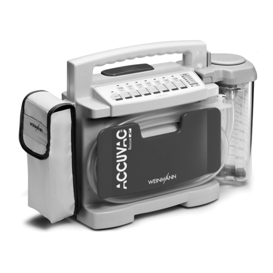
1. Overview ACCUVAC Rescue from front with reusable collection canister 4 Membrane keyboard 6 Re-usable collec- tion canister 5 Release catch 1 On/Off 2 Vacuum control switch 3 Capacity indicator 8 Tube holder plate 7 Motor unit ACCUVAC Rescue from rear without collection canister... - Page 4 ACCUVAC Rescue interior Re-usable collection canister 14 Fuse F100 15 Fuse F101 19 Vent tab 20 Filter cover 21 Bacteria filter 22 Locking tab 23 Bracing clip 24 Secretion cover 25 Ball (overfill guard) 26 Sealing ring 27 Nozzle with...
-
Page 5: Symbols On The Rating Plate
1.1 Symbols on the rating plate Symbol Meaning Serial number of device Year of manufacture Direct voltage CE symbol (confirms that the product conforms to the applicable European directives) Degree of protection against electric shock: appliance type BF IPX1 Protection against ingress of water Do not dispose of device in domestic waste 1.2 Symbols on the packaging Meaning... -
Page 6: Special Symbols On The Appliance
If the 10% LED lights up, it is time to recharge the ACCUVAC Rescue immediately (see “5.4 Charging the ACCUVAC Rescue” on page 26). If the 10% LED flashes, you must recalibrate the ca- pacity indicator (see “... -
Page 7: Description
• deflating vacuum matresses and inflatable splints. In expert hands, the ACCUVAC Rescue can elimina- te obstructions in the airways and so prevent the risk of respiratory failure. It can be used in buildings, in the open air and during transport. -
Page 8: Function
If the vacuum chang- es, the pump starts up again to restore the vac- uum to the preselected level. • ACCUVAC Rescue reduces energy consumption by reducing power when the vacuum has been reached. The aspirated material passes through the aspiration tube into the collection canister. - Page 9 The bacteria filter is designed for multiple re-use and sterilisation. Important Do not immerse the bacteria filter in disinfectant liq- uid, as this adversely affects its hydrophobic proper- ties. An overfill system prevents secretions from entering the motor unit. The ball floats on the surface of the secretion until it blocks the exit.
- Page 10 Power supply Power can be drawn: • from the built-in power pack. • from the WM 10650 connection cable using an available 12 Volt vehicle power supply. • from the FW7405M/14 mains/charger unit, complete WM 2610. The capacity indicator shows the charge status of the power pack in percent.
-
Page 11: Safety Instructions
Before starting to work with ACCUVAC Rescue, you must understand how to operate it. • ACCUVAC Rescue should be used only if you are medically qualified and have received training in aspiration techniques. Severe physical damage may be caused by incorrect use. - Page 12 • Have servicing and repair work performed only by the manufacturer, WEINMANN Emergency, or by professional staff. • To increase the service life of the power pack it should not be fully discharged. Please recharge...
- Page 13 • Do not use any cellphones in the immediate vi- cinity of ACCUVAC Rescue. It is possible to op- erate the ACCUVAC Rescue without any problems in the patient area of an ambulance, even if a cellphone is in use in the cab.
-
Page 14: Assembly
4. Assembly The ACCUVAC Rescue is supplied ready for use. Important Before using the ACCUVAC Rescue for the first time, fully charge the power pack (see “5.4 Charg- ing the ACCUVAC Rescue” on page 26). 4.1 Assembly with wall bracket... - Page 15 If the ACCUVAC Rescue appliance is switched off, it will automatically be charged up from the DC power source. 9. To remove the ACCUVAC Rescue from the wall bracket ready for use, press the release catch and lift the ACCUVAC Rescue out of the wall bracket.
-
Page 16: Fitting A Re-Usable Collection
4.2 Fitting a re-usable collection canister With the conversion kit WM 15261 you can also mount a re-usable collection canister instead of a disposable collection canister. 1. Disconnect the vacuum tube from the intake connector of the motor unit. 2. Remove the disposable collection canister from its holder. -
Page 17: Fitting A Disposable Collection
4.3 Fitting a disposable collection canister The conversion kit WM 15930 can be used to fit a disposable collection canister in place of a re-usable collection canister. 1. Remove the re-usable collection container from the motor unit. 2. Unscrew the holder from the motor unit. 3. -
Page 18: Inserting The Disposable Collection Bag
4.4 Inserting the disposable collection bag 1. Insert a new disposable collection bag. 2. Push a new aspiration tube onto the elbow connector of the disposable collection bag. 3. Switch on the device. 4. Set the vacuum of -0.8 bar on the device and connect the patient connection. -
Page 19: Fitting A Rinsing Glass
1. Use the velcro-type strips to attach the accessory bag to the loops on the motor unit. 4.6 Fitting a rinsing glass On the left side of the appliance it is possible to fit an additional collection canister in the form of a rinsing glass for holding a rinsing liquid, e.g. - Page 20 5. Fix the holder to the left side of the appliance. 6. Push the rinsing glass into the holder. Assembly...
-
Page 21: Operation
After switching on, all LEDs light up for one sec- ond. After that, only those LEDs that indicate the operating status stay on. 4. Preselect the desired vacuum by pressing the appropriate button. The ACCUVAC Rescue is now ready for operation, and you can start aspiration. Operation... -
Page 22: Aspiration
5.2 Aspiration • During the aspiration process, take care not to cause any injury to the patient’s mouth and throat region, and especially to mucous mem- brane. • The appliance can run for 60 minutes in continuous operation (S2 mode). Switch the appliance off after 60 minutes continuous operation to prevent overheating. -
Page 23: Venting The Re-Usable
secretion, it becomes impermeable and the dis- posable collection bag has to be replaced. Note • Keep an eye on the fill level of the collection ca- nister during aspiration with the reusable collec- tion canister. Empty the canister at a filling level of 850 ml so that the the overfill system does not become soiled and require cleaning. -
Page 24: Replacing The Disposable
Important When removing the collection canister, take care that the secretion cover is not opened accidentally, allowing the contents to spill over. 1. Unwind the aspiration tube from the tube holder plate to make it easier to remove the canister and reduce the risk of the secretion cover com- ing open by accident. -
Page 25: After Aspiration
Inserting the disposable collection bag” on page 18). 5.3 After aspiration After aspiration: 1. Switch off the ACCUVAC Rescue by pressing the button marked When running from the power pack, the button remains illuminated for about 4 minutes after switching off, so that it is easy to find for switch- ing the appliance on again when working in the dark. -
Page 26: Charging The Accuvac Rescue
23) or dis- pose of the disposable collection bag (see "Repla- cing the disposable collection bag" on page 24). 3. Clean the ACCUVAC Rescue (see “6. Hygienic preparation” on page 29). 5.4 Charging the ACCUVAC Rescue... - Page 27 12 V vehicle socket you must remove the red adapter ring. Caution: Check the vehicle plug for correct polarity. Reversed polarity can damage ACCUVAC Rescue. Note Once the device has been disconnected from the power source, the charging display may remain illu- minated for approx.
- Page 28 Charging with wall bracket 1. Switch off the ACCUVAC Rescue. 2. Insert the ACCUVAC Rescue in the wall bracket. 3. Charging starts automatically a few seconds af- ter you have switched on the power supply. This is indicated by moving lights on the LED capacity display, and is finished as soon as the moving lights stop and the 100 % LED lights up.
-
Page 29: Hygienic Preparation
FF (new) for immersion disinfection and ® terralin protect for wipe disinfection. Never immerse the ACCUVAC Rescue motor unit in disinfectant or other liquids. Always disinfect simply by wiping with disinfectant. Otherwise you may damage the device and thereby endanger users and patients (see “6.2 Cleaning, disinfecting and steriliz-... -
Page 30: Preparations
6.1 Preparations Re-usable collection canister Important When removing and emptying the re-usable collec- tion canister, take care that the secretion cover does not accidentally come off the collection canister and allow the contents to spill over. 1. Unwind the aspiration tube from the tube holder plate to make it easier to remove the canister and to reduce the risk of the secretion cover coming open by accident. -
Page 31: Disposable Collection
6. Remove sealing ring from groove in secretion cover. 7. Remove the filter cover. 8. Remove the filter. 9. Remove the tube holder plate by sliding it to the left to disengage it and then pulling it towards you. Disposable collection canister 1. -
Page 32: Cleaning, Disinfecting And
6.2 Cleaning, disinfecting and sterilizing Hygienic preparation of the ACCUVAC Rescue and the accessories used should be performed as de- scribed in the following table. Observe the instructions regarding use of disinfectant. -
Page 33: Reassembly
Rinse in washing Part Cleaning Disinfecting Sterilization machine Wipe with damp Motor unit Disinfectant wipe Not permitted cloth Rinse at up to Tube holder plate 40 °C 30 °C cycle in a In warm water with Immerse in dilute Not permitted washing machine a mild detergent solution... -
Page 34: Disposable Collection
3. Press sealing ring into groove in secretion cover. 4. Press the ball of the overfill system fully into its housing in the secretion cover. 5. Check the proper fit of bracing clip. 6. Place the secretion cover on the collection canister. - Page 35 3. Connect the collection canister to the intake connector of the motor unit via the vacuum tube. 4. Insert a new disposable collection bag (see “4.4 Inserting the disposable collection bag” on page 18). Hygienic preparation...
-
Page 36: Functional Check
(see ”8. Troubleshooting” on page 39). 7.1 Intervals To ensure that a properly functioning ACCUVAC Rescue is always available, it is essential to observe the following intervals. Before every use •... -
Page 37: Performing The Leak Check
– tube connections and disposable collection bag (disposable collection canisters). 3. Switch on the ACCUVAC Rescue. All LEDs light up for one second after switching on. After that, only those LEDs that indicate the operating sta- tus stay on. Check the charge level of the power... - Page 38 If neces- sary, recharge the power pack (see ”5.4 Charg- ing the ACCUVAC Rescue” on page 26). Stopper 4. Insert the stopper in the fingertip. 5. Use your thumb to hold the nozzle closed.
-
Page 39: Troubleshooting
8. Troubleshooting Fault Cause Remedy Appliance does not start. O/I indicator and capacity Have repairs carried out by factory or Faulty pump indicator show ready for by expert personnel operation Fuse F100 or F101 in appliance Fit new fuse (8.2, page 44) defective Fuse in vehicle plug defective Fit new fuse (8.2, page 44) -
Page 40: Power Pack
If unsuccessful, fit new power pack (8.1, page 40). Power pack at end of service life 8.1 Power pack The ACCUVAC Rescue is fitted with a high-grade nickel-cadmium power pack. Changing the power pack Important! Never touch the circuit board, as this can damage the electronic system. - Page 41 3. Remove the collection canister and any accessories. 4. If a reusable collection canister is used: unscrew the bracket. 5. If a disposable collection canister is used: unscrew the holder. 6. Open the case by unscrewing the 6 cross-head screws. When opening the case, be careful not to damage the silicone sealing cord.
- Page 42 The green 10% LED of the capacity indicator continues to flash until the electronic control sys- tem is synchronized with the power pack. Al- though the ACCUVAC Rescue will function when the power pack is charged, the indicator will not show the charge status of the power pack unless the system is calibrated.
-
Page 43: Calibrating The Capacity
10 % LED will carry on flashing for 4 min. Perform calibration as follows: 1. Charge the ACCUVAC Rescue for about 5 minutes. 2. Disconnect the ACCUVAC Rescue from the external power supply. -
Page 44: Changing Fuses
The green 10 % LED does not go out after emptying, but remains illuminated until the power pack has been fully charged for the first time. 6. Now connect the ACCUVAC Rescue to an exter- nal power supply in order to recharge it. The charging process takes about 2 hours. - Page 45 The minus lead of the cable is round and black. Caution: Check the vehicle plug for correct polarity. Reversed polarity can damage ACCUVAC Rescue. 2. Change the faulty fuse. Use only approved fuses (see “11. Technical Data” on page 51).
-
Page 46: Changing The Muffler
8.3 Changing the muffler 1. Use a screwdriver to unscrew the cover plate (2 cross-head screws). 2. Remove the old muffler. 3. Insert a new muffler. 4. Refit the cover plate. Make sure that the pad stuck to the cover plate is pressing against the muffler. -
Page 47: Maintenance
We recommend that you have any servicing, such as inspections and repair work, carried out by the man- ufacturer – WEINMANN Emergency – or by expert personnel. 9.2 Disposal To dispose of the unit properly, please contact a li- censed and certified electronic waste disposal mer- chant. -
Page 48: Scope Of Supply
10. Scope of supply 10.1 Standard scope of supply ACCUVAC Rescue with re-usable collection canister 1. ACCUVAC Rescue with re-usable collection canister, complete WM 10600 consisting of: – ACCUVAC Rescue, basic device – Re-usable collection canister, complete WM 10630 –... -
Page 49: Accuvac Rescue With
ACCUVAC Rescue with disposable collection canister 1. ACCUVAC Rescue with ® disposable collection canister Serres complete WM 10811 consisting of: – ACCUVAC Rescue, basic device – Disposable collection canister ® Serres , complete WM 10790 – Canister holder for Disposable ®... -
Page 50: Accessories
10.3 Spare parts You can order replacement parts separately if neces- sary. A current list of replacement parts can be or- dered on the Internet at www.weinmann- emergency.de or through your specialist dealer. Scope of supply... -
Page 51: Technical Data
11. Technical Data ACCUVAC Rescue ACCUVAC Rescue Appliance class 93/ Electromagnetic II b 42/EEC compatibility: – Radio EN 60601-1-2 370 x 280 x 140 (with re- interference usable collection canister) Dimensions suppression EN 55011 380 x 280 x 140 (with WxHxD in mm –... - Page 52 ACCUVAC Rescue ACCUVAC Rescue Disposable Average sound collection canister: pressure level at ≤ 62 dB(A) – Collection canister PC and thermoplastic -0.8 bar elastomer Materials – Secretion cover Re-usable collection – Disposable canister: collection bag Medical-grade PVC – Collection canister APEC –...
-
Page 53: Safe Distances
The ACCUVAC Rescue is intended for operation in an electromagnetic environment in which high-fre- quency interference variables are controlled. The customer or user of the ACCUVAC Rescue can help avoid electromagnetic interference by maintaining the minimum safe distance between portable and... -
Page 54: Warranty
12. Warranty Starting from the date of purchase, WEINMANN Emergency offers the customer a limited manufac- turer’s warranty on a new original WEINMANN Emergency product or replacement parts installed by WEINMANN Emergency in accordance with applica- ble warranty terms and conditions for the particular product and the warranty periods listed below. - Page 56 WEINMANN Emergency Medical Technology GmbH + Co. KG Frohboesestrasse 12 22525 Hamburg GERMANY E: customerservice@weinmann-emt.de www.weinmann-emergency.de T: +49 40 88 18 96-120 F: +49 40 88 18 96-481 Center for Production, Logistics, Service WEINMANN Emergency Medical Technology GmbH + Co. KG...
Need help?
Do you have a question about the ACCUVAC Rescue and is the answer not in the manual?
Questions and answers