Table of Contents
Advertisement
Advertisement
Table of Contents

Related Manuals for CARP-PORTER POWER-PORTER MK8

Summary of Contents for CARP-PORTER POWER-PORTER MK8
- Page 1 POWER-PORTER ASSEMBLY GUIDE CPP001 w w w . c a r p - p o r t e r . c o m...
-
Page 2: Table Of Contents
CONTENTS PARTS PARTS DIAGRAM REAR WHEEL ASSEMBLY 8 - 13 ADDING WHEELS TO FRAME 14 - 18 FRAME ASSEMBLY 19 - 23 CONNECTING TO BATTERY 24 - 26 HOW TO OPERATE 27 - 29 BATTERY LIFE AND CARE 30 - 31 FREE WHEEL 32 - 35 FINAL CHECKS... -
Page 3: Parts
PARTS CPS055 CPS026 CPS003 CPS054 A x 9 B x 1 C x 1 C x 1 CPS031 C x 2 C x 2 D x 2 CPS052 CPS053 E x 1 F x 2... - Page 4 CPS057 CPS056 CPS058 H x 1 G x 1 G x 1 CPS059 CPP001C J x 1 CPS060 I x 9 CPS058 K x 1 L x 2...
- Page 5 CPS058 CPP009 M x 1 N x 1 CPS061 CPS025 CPS015 Q x 1 O x 1 CPS020 M6 x 2 R x 1 M6 x 4 M6 x 2...
-
Page 7: Rear Wheel Assembly
REAR WHEEL ASSEMBLY WHAT YOU'LL NEED... CPS055 CPS054 M20 x 4 C x 1 C x 1 CPS031 C x 2 C x 2... - Page 8 STEP 1 Take the adjustable rear wheel leg (C) place on a washer, then the wheel and another washer. Make sure the air valve on the wheel is facing the same way as the adjustable leg holes. STEP 2 Fix figure of 8 pin to one end of axle shaft to secure in place, using the hole at the end of the axle.
- Page 9 STEP 3 The rear wheel assembly should be in the same sequence as shown. STEP 4 Complete the same process for the second rear wheel, with the valve facing away from the pin.
-
Page 10: Adding Wheels To Frame
ADDING WHEELS TO FRAME WHAT YOU'LL NEED... CPS060 M6 x 2 L x 2 CPS059 M6 x 2 M6 x 2 J x 1 CPP001C I x 9 C x 1 C x 1... - Page 11 STEP 1 Place frame (L) on the ground with fork lugs facing up. STEP 2 To fix the front wheel to frame position wheel assembly (I) on frame (L) locating axle uprights onto wheel fork lugs on frame. Make sure T screws on the wheel assembly are loose.
- Page 12 STEP 3 Be sure you are fixing the assembly on the correct way, there are 2 bolts and washers on the uprights they should be facing away from the frame. The uprights should slide right down to the base of the frame. STEP 4 Locate the short T screws on the inside of each upright and...
- Page 13 STEP 5 There are two holes on the front of the uprights place in long T screws (D) tighten and secure in place. STEP 6 Check the bolts on the other side of the uprights, making sure they are tight.
- Page 14 STEP 7 In order to attach the rear wheels take the rear leg bar (J) and fix to frame (L). Ensure the rear leg locking pin locates the corresponding hole in the side of frame. There are three locking pins on the assembly.
- Page 15 STEP 7 To fix the rear wheels to frame, attach rear leg assembly (C) onto leg bar (J). Ensure the holes on the adjustable leg are facing the same way as the locking pin and the flat side to the hand screw (P).
-
Page 16: Frame Assembly
FRAME ASSEMBLY WHAT YOU'LL NEED... CPS026 CPS058 H x 1 A x 9 CPS058 CPS003 B x 1 CPS015 CPS057 CPS056 M x 1 G x 1 G x 1 Q x 1 CPS053 CPS058 CPS052 F x 2 K x 1 E x 1... - Page 17 STEP 1 Turn the barrow over so its standing on its wheels. STEP 2 For the handle assembly take parts (M),(K),(H) and (B) place these together in the same order as shown in the diagram. Making sure the hand screws are all facing the same way as the one found on controller handle (M).
- Page 18 STEP 3 On the back of the assembly tighten all hand screws (P) to secure in place. STEP 4 Now you can attach the handle assembly to the frame (L), locating frame tubes with the arms. Use the hand screws (P) at either side of the frame and lock into place.
- Page 19 STEP 5 Place the side bars (F) into the frame tube either side of the barrow. Tighten hand screws (P) to lock in place. The side bars are interchangeable and will fit either side of the barrow. STEP 6 Take the front bar (E) and slide this into fork assembly (G).
- Page 20 STEP 7 Fix the front bar to frame (L) and lock into place with thumb screws (A). STEP 8 Place Y bar (Q) in the locator socket on the frame and tighten the two thumb screws (A) to set Y bar at desired height. You can adjust the height of the Y bar to suit different loading of tackle on the barrow.
- Page 21 CONNECTING ELECTRONICS WHAT YOU'LL NEED... CPP009 N x 1...
- Page 22 STEP 1 Locate the 2 connector plugs that meet at the back of the frame connecting the controller handle. Align the arrows up on each connector plug. STEP 2 The pins in the connector plug are delicate and should not be forced or pushed, this could lead to the pins bending and breaking.
- Page 23 STEP 3 When pressure is applied the bayonet connector will rotate down toward the unlock symbol to connect the pins and snap back into place, you should hear the snap on its return. This means its locked in and fully connected. STEP 4 Repeat the same process for the two...
- Page 24 STEP 5 If you need to disconnect the plugs, turn the bayonet towards the unlocked padlock symbol and pull to separate, initially you may feel some resistance but they will free up after a couple seconds. STEP 6 Place the battery (N) in the battery holder on the front wheel.
- Page 25 STEP 7 Once the battery is in place you can now connect the plugs locating from the front wheel to the battery, make sure the rotary dial on the hand controller is off before connecting, the plugs need to connect red to red and black to black as shown above.
-
Page 26: How To Operate
HOW TO OPERATE WHAT YOU'LL NEED... - Page 27 STEP 1 POWER/OFF AND SPEED Now that everything FORWARD is connected and LED INDICATOR ready for use familiarise yourself with the control unit. REVERSE Avoid heavy showers on your hand control unit and cover over night when leaving outside. STEP 2 Rotate the power dial clockwise, the led indicator should now...
- Page 28 STEP 3 The led light will show green if fully charged, amber will show low and red will flash for very low, if your light shows red or amber turn the dial to off mode and charge the battery. (See page 28 for charging instructions).
-
Page 29: Battery Life And Care
BATTERY LIFE & CARE WHAT YOU'LL NEED... CPS020 CPP009 R x 1 N x 1... - Page 30 HOW TO CHARGE YOUR BATTERY STEP 1 Plug in your battery charger, keep the plug socket off until you’ve attached the battery. Remove your battery pack from your barrow, making sure the power is off before disconnecting the battery and connect to the charger using the plugs, like before red to red and black to black.
- Page 31 OVERLOAD PROTECTOR Attached to your battery in the bag you have a switch current overload protector button, in the event of an overload this will protect the battery and trip out much like a fuse would. For example this can happen when you overload the circuitry on a big hill. If this does happen the Power Porter will lose power, simply press the reset button located on the battery, this will reinstate power and the led will light up.
-
Page 32: Free Wheel
FREE WHEEL WHAT YOU'LL NEED... IM FREE IM FREE! - Page 33 STEP 1 In the event of the battery failing it may be necessary to release the free wheel hub. First ensure the power is switched off, then release by pulling back and turning anticlockwise, the hub will disengage from the pins and free wheeling mode is possible.
- Page 34 FINAL CHECKS WHAT YOU'LL NEED... CPS061 O x 1...
- Page 35 STEP 1 Attached drop-in bag support frames to drop in bag, fixing in place under the velcro flaps. STEP 2 Place drop-in bag (O) into Carp Porter frame as shown, ensure the support frame inside the Velcro flaps locate in the bag retaining channel on the frame.
- Page 36 STEP 3 Once the bag is positioned correctly use the clips to secure the bag in place. STEP 4 Finally check all hand screws are tightened correctly, the front wheel is inflated to the correct pressure of 30 psi and the rear wheels are the corresct pressure of 25 psi, make sure the bolts and nuts on the front wheel and rear wheels are tight.
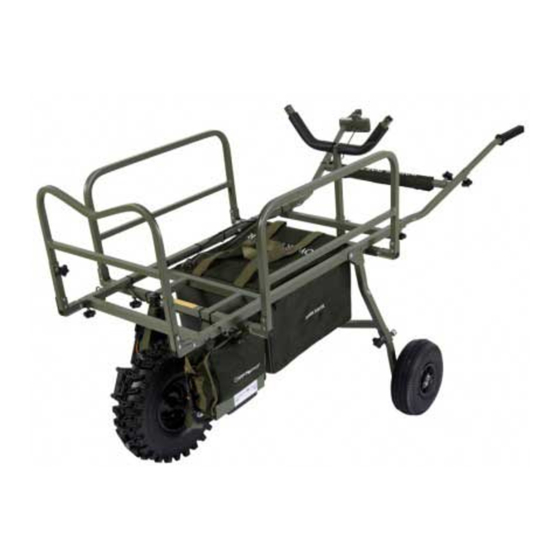
- Page 37 STEP 5 You should now have your fully assembled MK8 Power-Porter.
-
Page 38: Spare Parts
SPARE PARTS The MK8 Power Porter comes with a pack of spare parts, this pack contains : • Wheel bushes • 2 M12 Washers • 6 End caps • 7 Hand screws • 2 Wheel bearings • 2 Bungee straps •... -
Page 39: Disclaimer
DISCLAIMER IMPORTANT DO NOT OVER INFLATE THE WHEELS, CHECK THE MARKING ON THE TYRE FOR MAXIMUM INFLATION PRESSURE OF 30 PSI FOR THE FRONT WHEEL AND 25 PSI FOR THE REAR WHEELS. Your MK8 Power-Porter has been designed to provide years of trouble-free service.
Need help?
Do you have a question about the POWER-PORTER MK8 and is the answer not in the manual?
Questions and answers