Table of Contents
Advertisement
Quick Links
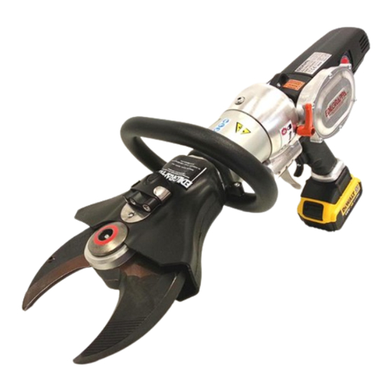
CORDLESS SHEAR F130N T30
18V Li-Ion
WITH ADJUSTABLE HEAD
No part of this manual may be reproduced or translated without the
written permission of the owner. The information and illustrations
©
contained in this manual are purely indicative. Edilgrappa S.r.l. reserves
the right to modify the machine without notice.
USE AND MAINTENANCE INSTRUCTIONS
Advertisement
Table of Contents
Troubleshooting

Related Manuals for EDILGRAPPA F130N T30


Summary of Contents for EDILGRAPPA F130N T30
- Page 1 No part of this manual may be reproduced or translated without the written permission of the owner. The information and illustrations © contained in this manual are purely indicative. Edilgrappa S.r.l. reserves the right to modify the machine without notice. USE AND MAINTENANCE INSTRUCTIONS...
- Page 2 Page...
- Page 3 COMBI TOOL AVAILABLE IN THE FOLLOWING VERSIONS: • 18V DIRECT CURRENT MOTOR FIXED HEADS AVAILABLE NAME OF MACHINE CORDLESS SHEAR F130N T30 18V Li-Ion SHEAR 1.50.2521 WITH ADJUSTABLE HEAD Page...
-
Page 4: Table Of Contents
CONTENTS Chap. 0 GENERAL INFORMATION ................ 6 0.01 FOREWORD 0.02 CONDITIONS OF SALE AND WARRANTY 0.03 SPECIAL SYMBOLS 0.04 SAFETY AND DANGER STICKERS - CE PLATE 0.05 LIST OF ACCESSORIES INCLUDED IN THE SUPPLY Chap. 1 REFERENCE LEGISLATION ..............9 1.01 GENERAL Chap. - Page 5 Chap. 7 TROUBLESHOOTING ................29 7.01 GENERAL 7.02 TROUBLESHOOTING THE MOTOR 7.03 TROUBLESHOOTING THE HYDRAULIC COMPONENTS Chap. 8 STORAGE AND RESTARTING ............... 31 8.01 STORAGE 8.01.01 ELECTRIC MOTOR 8.01.02 CYLINDER AND HYDRAULIC COMPONENTS 8.02 RESTARTING Chap. 9 DISPOSAL ....................32 Chap.
-
Page 6: Chap. 0 General Information
Chap. 0 GENERAL INFORMATION 0.01 FOREWORD This manual was drawn up to allow customers to optimise machine operation and should therefore be read in its entirety before use. The following chapters contain useful use and maintenance information. Knowledge and scrupulous observance of current occupational safety and plant engineering legislation is a fundamental requirements for correct use. -
Page 7: Special Symbols
0.03 SPECIAL SYMBOLS A brief legend indicating the most important symbols used in this manual is shown below. ATTENTION DANGER: highlights situations or problems that could lead to injury or death. IMPORTANT: highlights situations and problems connected with the efficiency of the machine that do not affect personal safety. -
Page 8: Safety And Danger Stickers - Ce Plate
0.04 SAFETY AND DANGER STICKERS - CE PLATE Position of plate and safety and danger stickers on the machine: Observe the warnings on the plates and stickers. Failure to do so could lead to injury or death. Make sure the plates and stickers are attached and legible. If not, apply them or request the maker for replacements. -
Page 9: List Of Accessories Included In The Supply
0.05 LIST OF ACCESSORIES INCLUDED IN THE SUPPLY • Case • Use and maintenance instructions • Declaration of conformity • Warranty certificate • Simple repair key, if appropriate Chap. 1 REFERENCE LEGISLATION 1.01 GENERAL This series of machines corresponds to the definition of machine to be found in the Machinery Directive 2006/42/EC. - Page 10 • Do not use naked flames or the like near the machine. • Do not use the machine in areas subject to the risk of fire or explosion. Foresee the possible consequences deriving from the use of the equipment in order not to be involved or involve other people in potentially hazardous situations.
-
Page 11: Electrical Safety
2.02. ELECTRICAL SAFETY Concerning the battery charger, consult the relative use and maintenance manual 2.03 PERSONAL SAFETY • The operator is responsible for safe machine operation. • Only allow the machine to be used by suitably trained and authorised adults. A When using an electric tool, operators must be alert, observe what they are doing and work with care. -
Page 12: Use And Maintenance Of Electric Tools
2.04 USE AND MAINTENANCE OF ELECTRIC TOOLS Do not force the tool. Use the right tool for the job to be done. Using the correct tool will assure improved and safer performance if used at the speed it was designed for. Do not use the tool if it cannot be switched on and off from its switch. - Page 13 • Do not alter the calibration of the safety devices (maximum pressure valves) • Do not service or clean the machine, or replace tools or guards while it is working. Do not remove the guards installed on the equipment and accessories. •...
-
Page 14: Chap. 3 Description Of Machine
Chap. 3 DESCRIPTION OF MACHINE 3.01 MACHINE COMPONENTS This machine is fitted with a direct current motor. The equipment comprises: - a motor, - a hydraulic pump driven by the motor, - a rod actuator (piston) driven by the oil pressured by the pump, - a fixed head with tool. -
Page 15: Chap. 4 Technical Specifications
Chap. 4 TECHNICAL SPECIFICATIONS 4.01 HYDRAULIC, MECHANICAL AND ELECTRICAL SPECIFICATIONS Maximum force in notch [ t ] 33.7 Maximum operating pressure [ bar ] Maximum blade aperture [ mm ] Dimensions: Length X Width X H ( with blades completely open and battery inserted ) [ mm ] 665 x 253 x 400 Weight ( with battery not inserted ) [ kg ] 12.15... -
Page 16: Chap. 5 Delivery, Commissioning And Set-Up
In the event of damage, send a written complaint to the forwarder within 8 days of receipt. Promptly inform Edilgrappa s.r.l. if major damage, caused during transport, is found upon receipt, or if any parts are missing. It is also necessary to check the delivered materials against the detailed shipping list. -
Page 17: Installing The Battery
ATTENTION: Only recharge the battery under surveillance and do not leave the charger unguarded. Never attempt to connect another type of battery to the connection terminals as this can irreparably damage the battery charger. Even if the battery remains under charge after the red LED turns off, it continues to be charged at a low maintenance current without suffering any damage. -
Page 18: Commissioning
5.04 COMMISSIONING The only controls to perform concern: Machine integrity: make sure that nothing happened during transport that could damage the insulation or mechanical parts. Make sure that the manual check valve is closed (paragraph 5.05). Completeness of supply: check that all the supplied accessories are fitted (battery charged and installed). Oil level: check the oil level and top up if necessary as per the instructions. -
Page 19: Cutting Phase
SWITCHING OFF (TOOL NOT OPERATIVE): To switch off the tool it is sufficient to hold down the main switch (Ref. A in fig.3B) for about 2 seconds (see sequence 1 in fig. 3A), until the leds light up (see sequence 2 in fig. 3A). The unlit leds indicate: tool not operative. - Page 20 Fig. 4 Page...
-
Page 21: Adjusting The Head
5.05.05 ADJUSTING THE HEAD The head of this machine can be adjusted (rotated by 180°) to help the operator during positioning and subsequent processing. To adjust the head, simply shift the release lever (ref. A in fig. 4A), as indicated by the arrow in sequence 1 to block the head;... - Page 22 Adjusting the head with the tool disconnected and not working. Hold the grip (ref. B in fig. 4A) and handle (ref. 3 in fig. 1) firmly, without touching the pivoting trigger, and move the head to the required position. Page...
-
Page 23: On/Off Trigger
5.06 ON/OFF TRIGGER The on/off trigger features the two positions indicated in fig. 2 Position 1: The piston moves for the blade opening phase. Position 2: The piston moves for the cutting phase. Fig. 2 Page... -
Page 24: Running Down The Battery
The machine cannot be used for cutting parts not specified above. Any use other than that expressly indicated shall be considered as improper and therefore not permitted. Edilgrappa S.r.l. declines all liability for any improper use of the machine and for any modification or change made to it. -
Page 25: Safety Devices
5.09 SAFETY DEVICES The machine is fitted with a safety device preventing contact with moving parts (levers and thrust fork) during the cutting phase; it also ensures protection against projected splinters and dangerous objects in the event of breakage of the thrust levers. It is a protective plastic guard secured to the machine with 2 screws (part 1 in fig. -
Page 26: Changing And Topping Up The Oil
Periodic maintenance schedule Frequency Person in Operation Method charge •CHECKING THE INTEGRITY OF THE EVERY 8 HOURS Visual Operator MACHINE EVERY 1600 Maintenance •CHANGING THE OIL Para 6.01 HOURS person •CHECKING THE TIGHTNESS OF NUTS EVERY 8 HOURS Para 6.02 Operator AND BOLTS •CHECKING BLADES FOR WEAR... - Page 27 TOPPING UP THE OIL: Before unscrewing the magnetic cap to check the oil level, make sure the piston is fully extended and, if necessary, pull it out (see fig. 4C). If this is not done the oil may leak, air bubbles may form and/or the oil level may be incorrectly measured, thus causing the machine to operate incorrectly.
-
Page 28: Checking Screws
6.02 CHECKING SCREWS Periodically, or every day in the event of frequent or prolonged work, make sure that all the screws are perfectly tight. FAILURE TO TIGHTEN LOCKING SCREWS CAN CAUSE SERIOUS DAMAGE. 6.03 CHECKING THE BLADES The use of worn blades decreases the potential of the machine and can needlessly overheat the motor. -
Page 29: Chap. 7 Troubleshooting
Chap. 7 TROUBLESHOOTING 7.01 GENERAL Faults can be divided into three sections: 1. faults on the motor 2. faults on the head 3. faults not closely connected with the machine ALL OPERATIONS MUST BE PERFORMED BY QUALIFIED PEOPLE IN OBSERVANCE OF SAFETY REGULATIONS. -
Page 30: Troubleshooting The Hydraulic Components
7.03 TROUBLESHOOTING THE HYDRAULIC COMPONENTS PERFORMED FAULT POSSIBLE REASON POSSIBLE REMEDY Damaged cursor Replace OUTWARD Max. pressure valve dirty Consult the Maker STROKE DOES Trigger damaged Replace NOT BEGIN Oil tank empty Fill Earth cable interrupted Repair MOTOR DOES NOT STOP Earth cable rusted Clean OUTWARD... -
Page 31: Chap. 8 Storage And Restarting
Chap. 8 STORAGE AND RESTARTING 8.01 STORAGE In case of long periods of inactivity, proceed as follows: 8.01.01 ELECTRIC MOTOR - Clean all the internal electrical parts (rotor, stator, cooling circuit) with compressed air DO NOT USE CONDUCTIVE OR FLAMMABLE LIQUIDS TO CLEAN INTERNAL ELECTRICAL PARTS - To clean the outside of the machine, if necessary, use a cloth dampened in soapy water and then dry thoroughly. -
Page 32: Chap. 9 Disposal
Chap. 9 DISPOSAL When disposing of the machine, the various materials must be separated. The tool comprises the following groups of materials: ferrous materials copper plastic Observe current legislation when sorting, storing, recycling or disposing of these materials. Only for EC countries: This electric tool is marked with the following recycling symbol. -
Page 33: Mechanical And Hydraulic Components
10.02 MECHANICAL AND HYDRAULIC COMPONENTS Exploded diagrams, code lists and wiring diagrams can be found on the following pages. SHEAR BLADES CUTTER F130N T30 18V P/N 150.02521 Page... - Page 34 SHEAR BLADES CUTTER F130N T30 18V P/N 150.02521 Position Part n. Description Q.ty 110,06057 Blade for F130N 110,05984 Blade pin 110,05788 Jaw link 160,00422 Seeger ring for shaft D=17 UNI 7435 110,05789 Blades yoke 110,04836 Positioning bushing for cutter and combi...
- Page 35 Position Part n. Description Q.ty 110,05226 Screw M8x9.4 terminal turned D.6.4x3 150,03172 Valve calibration for machine battery BO 36V 150.02630 Unlocking valve assembly 160,01036 Spring D.1xe7x6,25xL14 grounded 130,00242 Quad ring seal 8.2x1.78 110,01903 Control valve spool 110,02347 Setting headless screw 110,01518 Push spring screw for check valve 110,01546...
- Page 36 Position Part n. Description Q.ty 110,07752 Protection for handle cut pedals battery 18V 160,00937 Hex socket button head M5x10 10.9 UNI 7380 zinc plated 150,03361 Assembly engine machine battery DE 18V JE Page...
-
Page 37: Chap. 11 Declaration Of Conformity
For cutting cables, ropes, metal parts such as rods, sections, small pipes. Type: Cordless combi tool Model: CORDLESS F130N T30 Trade name: CORDLESS SHEAR F130N T30 18V Li-Ion with adjustable head Serial n°: ________________ Year of construction: ________________ DECLARES THAT THE ABOVE-MENTIONED EQUIPMENT IS COMPLIANT WITH THE FOLLOWING... - Page 38 NOTES: __________________________________________________________________________________________________________ __________________________________________________________________________________________________________ __________________________________________________________________________________________________________ __________________________________________________________________________________________________________ __________________________________________________________________________________________________________ __________________________________________________________________________________________________________ __________________________________________________________________________________________________________ __________________________________________________________________________________________________________ __________________________________________________________________________________________________________ __________________________________________________________________________________________________________ __________________________________________________________________________________________________________ __________________________________________________________________________________________________________ __________________________________________________________________________________________________________ __________________________________________________________________________________________________________ __________________________________________________________________________________________________________ __________________________________________________________________________________________________________ __________________________________________________________________________________________________________ __________________________________________________________________________________________________________ __________________________________________________________________________________________________________ __________________________________________________________________________________________________________ __________________________________________________________________________________________________________ __________________________________________________________________________________________________________ ___________________________________________________________________________________ Page...
- Page 39 Page...
- Page 40 MACHINES AND EQUIPMENT FOR THE BUILDING TRADE, INDUSTRY AND RESCUE 31030 BORSO DEL GRAPPA (TV) - ITALY - Via Callesello, 4 Tel. 0423 910122 – Fax 0423 542122 E-mail: cut@edilgrappa.com http: //www.edilgrappa.com Page...
Need help?
Do you have a question about the F130N T30 and is the answer not in the manual?
Questions and answers