Table of Contents
Advertisement
Quick Links
Advertisement
Table of Contents

Related Manuals for DUNIWAY Stockroom Terranova 926A


Summary of Contents for DUNIWAY Stockroom Terranova 926A
- Page 1 Terranova® 926A Dual Convection-enhanced Pirani Gauge Control Unit Instruction Manual rev1016NC © 2016 Duniway Stockroom Corp. Telephone: 650-969-8811 Toll-Free (US/Canada): 800-446-8811 Fax: 650-965-0764 Email: info@duniway.com Web: www.duniway.com...
-
Page 2: Table Of Contents
Table of Contents Specifications Accessories Introduction Installation Mounting the Terranova® 926A Connecting the Pressure Gauge Granville-Phillips Cable Conversion Operation Self Test Setup Mode Zero Adjustment Atmospheric Pressure Adjustment Changing Pressure Gauge Curve Restoring Default Values Pressure Measurement Set Point Operation Serial Communication Analog Output Troubleshooting... -
Page 3: Specifications
Specifications Universal: 100V to 240V AC @ 50Hz to 60Hz; 40VA Operating Voltage 100V to 240V DC Pressure Display 3 Red LEDs - 3 digits (NNN) with pressure unit auto ranging Pressure Units Torr/mTorr [Default] ; mbar/µbar 1 x 10 Torr to 1000 Torr ; (Air/Nitrogen) Measuring Range (1 x 10 mbar to 1000 mbar) -19 mTorr to 995 Torr; Display Range (-19 µbar to 995 mbar) Varies From: 0.1 mTorr below 100 mTorr (0.1 µbar below 100 µbar) - Page 4 Explosive Gases Do not use the Terranova® 926A to measure the pressure of combustible gas mixtures. Although the pressure gauge normally operates at low temperatures, it is possible that momentary transients or controller malfunction can raise the pressure gauge above the ignition temperature of combustible mixtures. This, in turn, can create an explosion which can damage equipment and/or injure personnel.
-
Page 5: Introduction
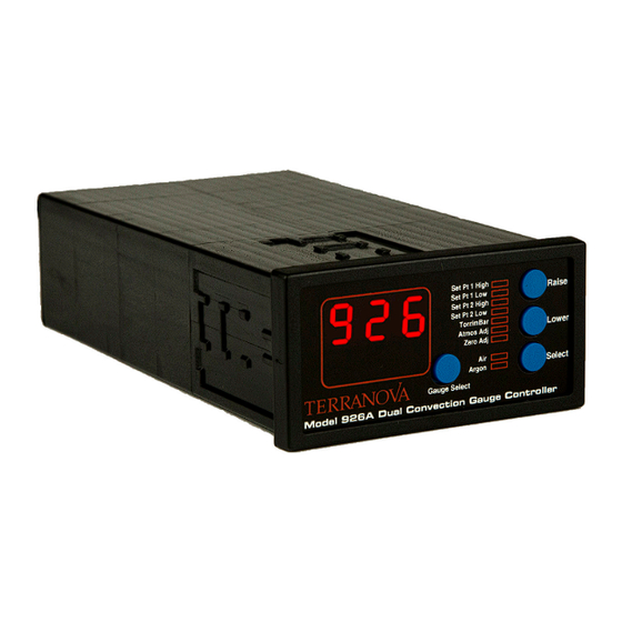
Introduction The Terranova® 926A Dual Convection Gauge Controller is designed to simultaneously operate two Granville-Phillips 275 Convectron® gauges, two MKS / HPS Series 317 convection-enhanced Pirani gauges, or two equivalent pressure gauges. The Terranova® 926A covers the pressure range between 1000 Torr to 1 x 10 Torr (1000 mbar to 1 x 10 mbar). Installation Mounting the Terranova® 926A The Terranova® 926A is housed in a standard 1/8 DIN box to allow for mounting on most equipment racks or cabinets. The dashed call-out dimensions in Figure 1 illustrate the proper cutout dimensions for the 1/8 DIN box. Figure 1 Terranova® 926A Dimensions To properly mount the unit: 1. -
Page 6: Connecting The Pressure Gauge
Connecting the Pressure Gauge The Terranova® 926A has a female 15-pin D-sub connection located on the back of the control unit labeled SENSOR(S) to connect the pressure gauge cable (See Figure 2). A dual cable is required to simultaneously connect both pressure gauges. User will require the Duniway gauge cable 275-CBL-2-10 to connect the Granville-Phillips 275 Convectron® gauges and equivalent pressure gauges to the control unit. Similarly, the user will require the Duniway gauge cable CEP-CBL-2-10 to connect the MKS / HPS Series 317 gauges or equivalent pressure gauges to the control unit. Figure 2 Terranova® 926A Back Panel The Terranova® 926A should be OFF before connecting the pressure gauge. Plugging or unplugging the pressure gauge while the control unit is ON can damage internal parts of the pressure gauge. -
Page 7: Granville-Phillips Cable Conversion
Granville-Phillips Cable Conversion Legacy Granville-Phillips 275 Convectron® control units that utilize gauge cables with an integrated AC power cord can be converted for use with the Terranova® 926A. To convert the gauge cable, the power cord must be removed and a male 15-pin D-sub connector should be installed at the control unit cable end. See Appendix 2 for Granville-Phillips 275 Convectron® gauge (and equivalent) cable configuration. Operation Self Test The Terranova® 926A will perform a self test at power ON. The Self Test cycle is initiated by a BEEP sound followed by: 1. All LEDs momentarily illuminate 2. Numeric display indicators and mBar LED become illuminated 3. Pressure unit LEDs become illuminated 4. Pressure gauge LED indicators become illuminated 5. -
Page 8: Zero Adjustment
Although the SET PT HIGH and SET PT LOW parameter may be independently assigned to operate with either pressure gauge, both values will apply to the pressure gauge selected for the SET PT LOW value. Use the GAUGE SELECT button to choose between GAUGE 1 and GAUGE 2. 5.Press the SELECT button a fifth time to set the pressure units for both pressure gauges. Use the RAISE or LOWER button to select between torr and millibar pressure units. Default pressure unit is Torr. The corresponding pressure unit LEDs will illuminate during adjustment. 6. Press the SELECT button a sixth time to adjust the atmospheric pressure value. Use the RAISE or LOWER button to increase or decrease the ATMOS ADJ pressure value shown on the display. ATMOS ADJ LED will illuminate during adjustment. See Atmospheric Pressure Adjustment. 7. Press the SELECT button a seventh time to zero-adjust the control unit. Use the RAISE or LOWER button to increase or decrease the ZERO ADJ pressure value shown on the display. Zero ADJ LED will illuminate during adjustment. -
Page 9: Atmospheric Pressure Adjustment
Negative pressure readings during use or zero adjustment may indicate the control unit requires further adjustment. Negative pressure readings are to be used only as an indication of vacuum. Atmospheric Pressure Adjustment Atmospheric pressure adjustment is recommended when installing a new pressure gauge or to restore pressure output accuracy. The Terranova® 926A can be set to either local atmospheric pressure – 760 Torr (1013 mbar) at sea level – or a specific high pressure value via the ATMOS ADJ pressure value. Pressure reading must be greater than approximately 260 Torr (350 mbar) at initial set-up to adjust the ATMMOS ADJ value. Error Code E12 will be output if pressure reading is less than approximately 260 Torr (350 mbar). Zero adjustment should be conducted before the atmospheric pressure adjustment. If millibar units are to be used, ATMOS ADJ value adjustment should be conducted in Torr units. Although ATMOS ADJ pressure value is stored by the control unit, it will not be displayed in subsequent adjustments. ATMOS ADJ value is appropriately converted when switching between pressure units. Pressure reading range will shift if user accidentally changes ATMOS ADJ value during use. If this occurs, user should reset the Terranova® 926A and redo both the zero and atmospheric pressure adjustment. -
Page 10: Pressure Measurement
Once power is restored, the unit will commence the Self Test. If reset process is successful, two BEEPs will be emitted and the code “RST” will appear on the display. Thereafter, the Terranova® 926A will resume normal operation. Restoring default parameters will not affect the selected pressure unit Pressure Measurement Terranova® 926A operation is almost automatic and will commence after a successful Self Test. Pressure units will auto range during use as system pressure increases or decreases. The Terranova® 926A is set to output pressure readings based on air/nitrogen. If gases other than air/nitrogen are to be used, Appendix 3 provides corrected pressure values for a number of gases including argon with respect to air/nitrogen. For example, if the vacuum system is backfilled with carbon dioxide (CO ) and the Terranova® 926A reads a vacuum pressure of 29.4 Torr, true system pressure is approximately 500 Torr. Although the Terranova® 926A is able to simultaneously operate two pressure gauges, only one pressure gauge reading will be displayed at a time. User can select between GAUGE 1 and GAUGE 2 using the GAUGE SELECT button to display the corresponding pressure readings. The selected pressure gauge LED will illuminate during use. Unit display will read OFF if gauge cable is disconnected. Unit display will read HI if system pressure is greater than 995 Torr or if the pressure guage is disconnected, but the gauge cable is connected to the unit. Display will read LO if system pressure is less than the minimum allowed pressure value by the control unit. Terranova® 926A pressure display resolution is as follows: Step Range 5 Torr greater than 100 Torr 0.5 Torr... -
Page 11: Set Point Operation
Set Point Operation The Terranova® 926A can be utilized for process control functions through the use of two independent, programmable set points, SET POINT 1 and SET POINT 2, and corresponding relays. Each set point has an ad- justable activation (e.g. SET POINT LO) and deactivation (i.e. SET POINT HI) pressure value that allows the user to modify the relay hysteresis. SET PT 1 HIGH and SET PT 1 LOW correspond to SET POINT 1; SET PT 2 HIGH and SET PT 2 LOW correspond to SET POINT 2. Set point pressure values are adjusted via the front panel; relay output is accessible through the INPUT / OUTPUT 15-pin D-sub connector port located in the back of the control unit. See Table 1 for relay pin configuration. Each relay will independently activate once the pressure reading is less than its corresponding SET POINT LOW value. The relay will deactivate once the pressure reading is greater than its corresponding SET POINT HIGH value. Relays will be disabled if set point value is OFF. The Terranova® 926A will automatically increase the SET POINT HIGH value to the next pressure step from the SET POINT LOW value if SET POINT LOW is adjusted greater than SET POINT HIGH and vice versa. For example, if SET POINT HIGH is set to 100 Torr and SET POINT LOW is set to 110 Torr, the SET POINT HIGH value will automatically be adjusted to 115 Torr. See Appendix 4 for relay use with inductive or capacitive load switching. Terranova® 926A set point pressure display resolution is as follows: Step Range 5 Torr greater than 100 Torr 0.5 Torr 100 Torr to 10 Torr... -
Page 12: Serial Communication
Serial Communication The INPUT/OUTPUT 15-pin D-sub port allows the user to remotely query the Terranova® 926A to read unit parameter values. The serial communication standard used for data transmission is RS-232. The RS-232 format for communication with the Terranova® 926A unit is as follows: RS-232 Settings 9600 baud No parity 8 bits 1 stop bit Full duplex Figure 4 illustrates the pin configuration for RS-232 communication. User will require the Duniway cable RS232-TN9DIN and a separate program, such as HyperTerminal, to send query characters and read output from the control unit. Query applies to both pressure gauges regardless of which gauge is selected on the control unit display. Table 2 lists the characters used by the Terranova® 926A to return unit parameters. RS-232 Standard 9-Pin Terranova®... -
Page 13: Analog Output
Depending on selected unit, output values are either in torr or millibar Character Query Output Format Notes SET POINT 1 value AeB XeY R G ASCII value 49 SET POINT 2 value AeB XeY R G ASCII value 50 Gas response curve Air, Argon ASCII value 103 Pressure reading AeB XeY ASCII value 112 Pressure units Torr/mBar ASCII value 117 Model number;... -
Page 14: Troubleshooting
where P is the pressure reading in mTorr (or μbar) and V is the analog output voltage in volts. For example, if P is equal to 10.0 mTorr, V (rounded to nearest hundredth) is equal to 1.50 V. Table 3 lists sample analog output and corresponding pressure values. Analog Output [V] Pressure 0.00 LO/P ≤ 0 mTorr 0.50 0.10 mTorr 1.00 1.0 mTorr 1.50 10.0 mTorr 2.00 100 mTorr 2.50 1 Torr 3.00 10 Torr 3.50 100 Torr 4.00 OFF/HI Table 3 Analog Output and calculated pressure values Pressure as a function of the analog output can be approximated by: P = 0.01 * 10 where V is the analog output in volts and P is pressure in mTorr (or μbar). For example, if V is equal to 2.50 V, P (rounded to the nearest one) is 1.00 Torr (or 1.00 mbar). - Page 15 Pressure Gauge The Granville-Phillips 275 Convectron® gauge and MKS / HPS Series 317 gauge have internal resistance values indicative of an operational pressure gauge. User should first reset the Terranova® 926A to correct any controller problems. If resetting does not resolve the problem, user may clean the inside of the pressure gauge. A cleaning agent such as acetone or toluene may be used to carefully clear away any contaminants. The pressure gauge should be replaced if resistances greatly deviate or if cleaning does not provide reasonable pressure readings.
- Page 16 MKS/HPS Series 317 Convection-enhanced Pirani Gauge 1 2 3 4 5 6 7 8 9 Figure 6 MKS/HPS Series 317 gauge pin configuration Resistance [Ω] 1 & 7 1 & 8 5 & 7 Table 5 MKS/HPS Series 317 gauge resistance values If the measured resistance values significantly differ from those provided in Table 5, the pressure gauge may be damaged, contaminated, or defective. Tests should be performed at atmospheric pressure and room temperature (e.g. 20 °C). Tests should not be performed with instruments which output greater than 5 mA. 1. Brooks Automation, Inc. ‘Granville-Phillips® Series 475 Convectron® Vacuum Measurement Controller Instruction Manual’. 2009.
-
Page 17: Changing Fuses
Changing Fuses The Terranova® 926A contains two Type F, regular (or slow-blow) 1 A fuses. As shown in Figure 6, both fuses are held in the fuse assembly located on the back panel of the unit. Figure 6 MKS/HPS Series 317 gauge & pin layout To change fuses: 1. Unplug the line cord from the unit power module 2. Locate the fuse block immediately below the power cord socket 3. Press the tab of the fuse block and withdraw the assembly 4. Inspect and replace faulty fuse(s) 5. Reinsert fuse assembly into power module 6. Push fuse assembly into place until assembly tabs “click” The following is a list of suggested replacement fuses: Recommended Fuses Bussman GDB-1A... -
Page 18: Warranty
Warranty Duniway Stockroom Corporation (“DSC”) warrants all Terranova® products to be free of defects in material and workmanship for a period of one year from the date of shipment. At our option, we will repair or replace products which prove to be defective during the warranty period. Liability under this warranty is limited to repair or replacement of the defective item(s). Shipping damage is excluded from the scope of this warranty. Pressure gauges of all types are excluded from this warranty. Terranova® products are warranted not to fail to execute programming instructions due to defects in materials and workmanship. If DSC receives notice of such defects during the warranty period, DSC will repair or replace firmware that does not execute its programming instruction due to such defects. DSC does not warrant that the operation of the firmware or hardware will be uninterrupted or error-free. If this product is returned to DSC for warranty service, Buyer will prepay shipping charges and pay all duties and taxes for products returned to DSC. DSC will pay for the return of products to Buyer, except for products returned to a Buyer from a country other than the United States. Limitation of Warranty The foregoing warranty does not apply to the defects resulting from: 1. Improper or inadequate maintenance by the Buyer 2. Buyer-supplied interfacing 3. Unauthorized modification or misuse 4. Operation outside of the environmental specifications of the product 5. -
Page 19: Declaration Of Conformity
Declaration of Conformity Duniway Stockroom Corp. declares under its sole responsibility that the following products: Terranova 906A Convection Gauge Controller Terranova 908A Dual Capacitance Diaphragm Gauge Controller Terranova 926A Dual Convection Gauge Controller which display the CE mark to which this declaration relates are in conformity with the following standards or normal documents: EMC Directive (89/336/EEC//93/68/EEC) Electromagnetic Compatibility Standards: EN 50081-1: 1992, EN 50082-1: 1993 EN 61326: 1997/A1: 1998/A2: 2002 Low Voltage Directive (73/23/EEC//93/68/EEC) Electrical / Technical Safety Standard: EN 61010-1: 1993/A2: 1995: 2001 following the provisions of the EMC directive (89/336/EEC) UL and CSA Listing Safety of Electrical Equipment for Laboratory Use Conforms to UL61010A-1, Issued 2002/01/30 Certified to CAN/CSA C22.2 No. 1010.1-92, 97 Telephone: 650-969-8811... -
Page 20: Appendix 1 Terranova 926®A Compatible Pressure Gauges
Appendix 1 Terranova® 926A Compatible Pressure Gauges Duniway Part No. Description Fitting GP275-071 Granville-Phillips 275 Convectron® gauge 1/8" Male NPT CVT-275-101 Duniway Convection-enhanced Pirani gauge 1/4" Female VCR CVT-275-133 Duniway Convection-enhanced Pirani gauge 1/8" Male NPT CVT-275-KF25 Duniway Convection-enhanced Pirani gauge KF25 CVT-275-VCR-4 Duniway Convection-enhanced Pirani gauge Mini Conflat CEP-HPS-SH MKS/HPS Series 317 Shielded Convection-enhanced Pirani gauge 1/8" Male NPT CEP-HPS-KF16SH MKS/HPS Series 317 Shielded Convection-enhanced Pirani gauge KF16 ** Other fittings available upon request... -
Page 21: Appendix 2 Gauge Cable Diagrams
Appendix 2 Gauge Cable Diagrams GP 275 Convectron® Terranova® 926A Gauge Control Unit Gauge 1 Gauge 2 Pin 7 Pin 13 Pin 1 Pin 14 Pin 8 Pin 11 Pin 2 Pin 5 Pin 2 Pin 15 Drain/Shield Pin 9 Pin 3 Pin 3 Pin 4... -
Page 22: Appendix 3 Corrected Pressure Values For Gp 275 Convectron® Gauge
Appendix 3 Corrected Pressure Values for GP 275 Convectron® Gauge True Pressure Indicated Pressure [Torr] [Torr] Deuterium Freon-22 Methane Oxygen 1 x 10 1.00 x 10 1.00 x 10 1.00 x 10 1.00 x 10 1.00 x 10 1.00 x 10 2.00 x 10 1.00 x 10 1.00 x 10 2 x 10 1.00 x 10 2.00 x 10... -
Page 23: Appendix 4 Notes On Terranova® Set Point Relays
Appendix 4 Notes on Terranova® Set Point Relays Figure 1 Heavy Duty Type AZ5 relay voltage-current relationship The Heavy Duty Type AZ5 relay is used in the Terranova 926A to control external functions. As shown in Figure 1, maximum current varies from 2 A at 30 V DC (60 V AC) to 0.4 A at 150 V DC (300 V AC) for resistive loads. Protective Circuits for Inductive Loads A protective circuit or component is recommended when switching inductive loads to suppress sudden voltage spikes. One method to suppress high voltage spikes in an AC circuit is through the use of a “snubber” circuit. A “snubber” circuit consists of a capacitor and resistor across an inductive load. As shown in Figure 1, the “snubber” circuit is parallel to the high-current relay. - Page 24 Appendix 4. Notes on Terranova® Set Point Relays Figure 2 Example of a "snubber" circuit To calculate the appropriate capacitor C in microfarads [µF] and resistor R in ohms [Ω] to use in the “snubber” circuit, Paktron Capacitors’ Quencharc® technical note suggests the following empirical equations: /10 (1), and R=E/10I(1+50/E) (2), where I is the load current prior to contact opening in amperes [A] and E is the source voltage in volts [V]. For example, if Figure 2 shows a 1 A high-current relay with a 110 V AC source connected in series with the Terranova relay, I = 1 A and E = 110 V AC. Therefore, Equation 1 provides a capacitance value of 0.1 µF; Equation 2 provides a resistance value of approximately 8 Ω. Thus, a 0.1 µF capacitor and a 10 Ω resistor should be used for the “snubber” circuit. However, user must take into consideration the voltage and power rating of the capacitor and resistor, respectively, to meet the requirements of the circuit. Similar protective circuits or components should be considered to suppress current spikes in capacitive loads. Pancon Corporation. ‘2012 Catalog’. 2012. 18-19. Web. http://www.panconcorp.com/PDFs/Catalogs/Paktron_2012catalog.pdf Telephone: 650-969-8811 Toll-Free (US/Canada): 800-446-8811 Fax: 650-965-0764 Email: info@duniway.com Web: www.duniway.com...
Need help?
Do you have a question about the Terranova 926A and is the answer not in the manual?
Questions and answers