Table of Contents
Advertisement
Quick Links
Advertisement
Table of Contents

Subscribe to Our Youtube Channel
Summary of Contents for Sennheiser AC 3200 - 09-08
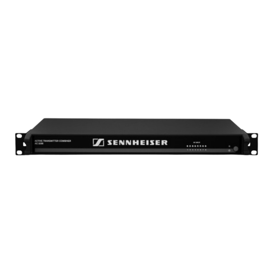
- Page 1 Active Transmitter Combiner 8:1 AC 3200 Instruction manual...
-
Page 3: Table Of Contents
Contents Contents Important safety instructions ............. 2 The AC 3200 active transmitter combiner 8:1 ......5 Delivery includes ................5 Connection diagram ............... 6 Product overview ................7 Putting the AC 3200 into operation ........... 8 Preparing the AC 3200 for use ..........8 Connecting the antenna ............ -
Page 4: Important Safety Instructions
15. To completely disconnect the device from the AC mains, disconnect the mains plug from the AC receptacle. 16. WARNING: To reduce the risk of fire or electric shock, do not expose the device to rain or moisture. 17. Do not expose the device to dripping or splashing and ensure that no objects filled with liquids, such as vases or coffee cups, are placed on the device. - Page 5 Hazard warnings on the rear of the AC 3200 active transmitter combiner 8:1 The label shown on the left is attached to the rear of the AC 3200. The symbols on this label have the following meaning: This symbol is intended to alert the user to the presence of uninsulated dangerous voltage within the AC 3200’s enclosure...
- Page 6 “Important safety instructions” on page 2, using the device within the operating conditions and limitations described in this instruction manual. “Improper use” means using the device other than as described in this instruction manual, or under operating conditions which differ from those described herein.
-
Page 7: The Ac 3200 Active Transmitter Combiner 8:1
The AC 3200 active transmitter combiner 8:1 The AC 3200 active transmitter combiner 8:1 With the AC 3200 active transmitter combiner, the signals of up to eight Sennheiser wireless monitoring transmitters can be combined onto a single antenna, e.g. the A 2003 UHF directional antenna, the A 1031 U omni-directional antenna or the A 5000 CP circularly polarized UHF antenna. -
Page 8: Connection Diagram
Connection diagram Connection diagram The below connection diagram shows the connections for an 8-channel system with a single antenna. AC 3200... -
Page 9: Product Overview
Product overview Product overview » 70 W Rack mount “ears” Air vents (on the sides) 8 LEDs: operation indicators of the RF inputs On/off switch IEC mains socket 8 RF inputs RF IN 1 RF IN 8 for connecting the transmitters... -
Page 10: Putting The Ac 3200 Into Operation
Putting the AC 3200 into operation Putting the AC 3200 into operation Preparing the AC 3200 for use You can set up the AC 3200 on an even surface or mount it into a 19" rack. Setting up the device CAUTION! - Page 11 Ensure that the base of the AC 3200 is clean and free from grease before fitting the rubber feet. Fix the rubber feet to the base of the AC 3200 by peeling off the backing paper and fitting them as shown in the diagram on the left.
-
Page 12: Connecting The Antenna
AC 3200! The AC 3200 active transmitter combiner can be used with either the A 2003 UHF directional antenna, the A 1031 U omni- directional antenna or the A 5000 CP circularly polarized UHF antenna. The antenna transmits the signals of all connected transmitters (see page 12). -
Page 13: Connecting The Mains Cable
Connect the suitable mains cable to the IEC mains socket and to the mains. Note: 70 W The AC 3200 can be connected to any mains power supply with 100 V to 240 V AC (50 to 60 Hz). Switching the AC 3200 on and off »... -
Page 14: Recommendations And Tips For Optimum Reception
Do not use any solvents or cleansing agents. Before cleaning, disconnect the device from the mains. Only use a slightly damp cloth to clean the device. Regularily check the air vents for dust deposits. If necessary, remove the dust with a soft brush. -
Page 15: If A Problem Occurs
If a problem occurs that is not listed in the above table or if the problem cannot be solved with the proposed solutions, please contact your local Sennheiser agent for assistance. -
Page 16: Accessories And Spare Parts
The following accessories are available from your Sennheiser partner: Cat. No. Accessory/spare part 003658 A 2003 UHF passive directional antenna 004645 A 1031 U passive omni-directional antenna 500887 A 5000 CP circularly polarized UHF antenna 002324 GZL 1019-A1 BNC-BNC coaxial cable, type RG 58, length 1 m... -
Page 17: Specifications
100 mW per input inputs protected up to max. 250 mW 50 Ω Impedance Power supply 100 V – 240 V AC, 50 – 60 Hz Power consumption max. 70 W Temperature range 0 °C to 45 °C Weight approx. -
Page 18: Manufacturer Declarations
(2) this device must accept any interference received, including interference that may cause undesired operation. This equipment has been tested and found to comply with the limits for a Class B digital device, pursuant to Part 15 of the FCC Rules. These limits are designed to provide reasonable protection against harmful interference in a residential installation. - Page 20 Sennheiser electronic GmbH & Co. KG Am Labor 1, 30900 Wedemark, Germany Phone: +49 (5130) 600 0 Printed in Germany Fax: +49 (5130) 600 300 Publ. 09/08 www.sennheiser.com 528244/A01...


Need help?
Do you have a question about the AC 3200 - 09-08 and is the answer not in the manual?
Questions and answers