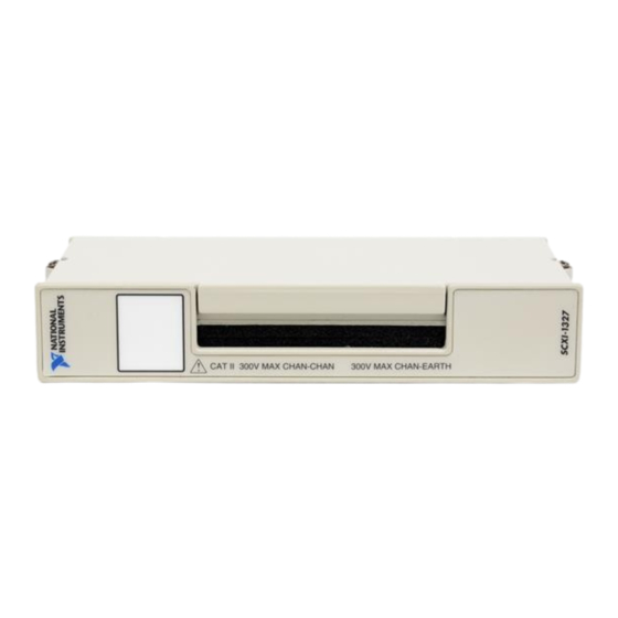
National Instruments SCXI-1327 Installation Manual
High-voltage attenuator terminal block
Hide thumbs
Also See for SCXI-1327:
- Installation manual (16 pages) ,
- Instructions for safe use (4 pages)
Table of Contents
Advertisement
Quick Links
INSTALLATION GUIDE
SCXI-1327 H
T
B
ERMINAL
Introduction
What You Need to Get Started
CVI ™ , LabVIEW ™ , NI-DAQ ™ , and SCXI ™ are trademarks of National Instruments Corporation. Product and company names are trademarks or
trade names of their respective companies.
321930A-01
-V
IGH
OLTAGE
LOCK
This guide describes how to install and use the SCXI-1327 high-voltage
attenuator terminal block with the SCXI-1120 and SCXI-1121 modules.
The SCXI-1327 high-voltage attenuator terminal block is a shielded board
with screw terminals that connect to the SCXI-1120 or SCXI-1121 input
connector. Each SCXI-1327 channel has a precision 100:1 resistive voltage
divider that you can use to measure voltages of up to 250 Vrms. You can
individually bypass these dividers for low-voltage measurement
applications.
The terminal block has 18 screw terminals for easy connection. One pair of
screw terminals connects to the SCXI-1120 or SCXI-1121 chassis ground.
When used with the SCXI-1120, the remaining eight pairs of screw
terminals are for signal connection to the eight module inputs. When used
with the SCXI-1121, four pairs of SCXI-1327 screw terminals are for
connecting signals from the four module inputs and four pairs of
SCXI-1327 screw terminals are for connecting signals from the module
excitation channels.
To set up and use your SCXI-1327 terminal block, you will need the
following items:
SCXI-1327 high-voltage attenuator terminal block
SCXI-1327 High-Voltage Attenuator Terminal Block Installation
Guide
SCXI chassis
© Copyright 1998 National Instruments Corp. All rights reserved.
A
TTENUATOR
August 1998
Advertisement
Table of Contents

Summary of Contents for National Instruments SCXI-1327
- Page 1 SCXI-1327 High-Voltage Attenuator Terminal Block Installation Guide SCXI chassis CVI ™ , LabVIEW ™ , NI-DAQ ™ , and SCXI ™ are trademarks of National Instruments Corporation. Product and company names are trademarks or trade names of their respective companies. 321930A-01 ©...
-
Page 2: Safety Information
O NOT SUBSTITUTE PARTS OR MODIFY EQUIPMENT introducing additional hazards, do not install unauthorized parts or modify the device. Return the device to National Instruments for service and repair to ensure that its safety features are not compromised. When using the device with high common-mode voltages, you... - Page 3 Temperature Sensor Output and Accuracy The SCXI-1327 temperature sensor outputs 1.91 to 0.58 V from 0° to 55° C and has an accuracy of ±0.5° C over the 15° to 35° C range and ±0.9° C over the 0°...
- Page 4 100 before the voltage enters the module. • Set both switches to the 1:1 position to bypass the attenuator of the appropriate channel. This setting removes the 100:1 divider from the input stage. SCXI-1327 Installation Guide © National Instruments Corporation...
-
Page 5: Signal Connection
Refer to the Safety Information section before removing equipment covers or connecting or disconnecting any signal wires. When connecting your signals to the SCXI-1327, follow the labeling on the SCXI-1327 for the appropriate module, as indicated in Figure 2. To connect the signal to the terminal block, perform the following steps, referring to Figures 1 and 2 as necessary: Unscrew the top cover screws and remove the cover. - Page 6 Reinstall the top cover and tighten the top cover screws. 10. Connect the terminal block to the module front connector as explained in the Installation section later in this guide. Figure 1 shows the SCXI-1327 terminal block parts locator diagram. Back View Front View...
-
Page 7: Installation
Figure 2 shows the SCXI-1327 signal connections. 1 Channel Labeling for the 4 Switches to Enable or Bypass the 7 Serial Number SCXI-1121 Attenuator 8 Chassis Ground 2 Channel Labeling for the 5 Product Name, Assembly 9 Thermistor SCXI-1120 Number, and Revision Letter... -
Page 8: Specifications
Resistance ........1 MΩ Temperature Sensor Circuit Diagram You do not need to read this section to operate the SCXI-1327. The circuit diagram in Figure 3 is optional information that you can use if you want more details about the SCXI-1327 temperature sensor.


Need help?
Do you have a question about the SCXI-1327 and is the answer not in the manual?
Questions and answers