Panasonic SF4C Series Manual
Ultra-slim light curtain, type 2/4 ple sil1/sil3
Hide thumbs
Also See for SF4C Series:
- Instruction manual (93 pages) ,
- Instruction manual (143 pages) ,
- Quick instruction manual (116 pages)
Table of Contents
Advertisement
Quick Links
Discover which Ultra-slim light curtain will significantly
enhance your machine safety protocols while
optimizing productivity
Reach out to Ramco Innovations now for any inquiries!
2016.03
www.PanasonicSensors.com
Ramco Innovations www.PanasonicSensors.com
Machine safeguarding without sacrificing productivity
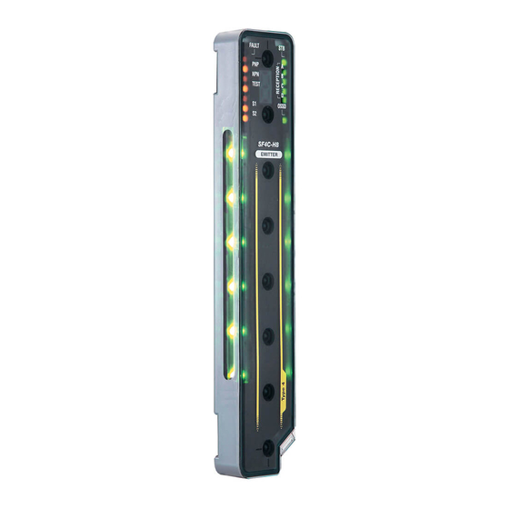
Ultra-slim Light Curtain
Ultra-slim
LIGHT CURTAIN
SF4C
Type 4 PLe SIL3
SF2C
Type 2 PLc SIL1
Conforming to Machine
Certified
& EMC Directive
Conforming to
OSHA / ANSI
[SF4C-H -J05) only]
Featuring easy beam axis
alignment and reduced wiring
Introducing Type 2
(800) 280-6933
SERIES
SERIES
Certified by
NRTL
Certified
* The picture is an image.
Advertisement
Table of Contents

Related Manuals for Panasonic SF4C Series


Summary of Contents for Panasonic SF4C Series
- Page 1 Ultra-slim LIGHT CURTAIN SF4C Type 4 PLe SIL3 SERIES SF2C Type 2 PLc SIL1 Discover which Ultra-slim light curtain will significantly SERIES enhance your machine safety protocols while optimizing productivity Conforming to Machine Certified Certified by & EMC Directive NRTL Conforming to Reach out to Ramco Innovations now for any inquiries! OSHA / ANSI...
- Page 2 Max. (Factory setting is mounted.) 640 mm 25.197 in Min. 160 mm 6.299 in Hand protection type of SF4C series 13.2 mm 0.520 in SF4C (with mounting bracket) 43 mm 1.693 in Previous model (with mounting bracket) * Usable work space is 60 mm 2.362 in...
- Page 3 The indicator can be used as an operation indicator, job indicator, etc. Indicator color, SF4C series: green and red SF2C series: orange Performance comparison of SF4C / SF2C series...
- Page 4 The finger type ( ) has a 10 mm beam pitch which allows additional protection SF2C-H while reducing overall size. Hand protection type Finger protection type SF4C series Safety distance Characteristic Characteristic safety distance Shortened by Hand protection type 102mm...
- Page 5 Input 2 Operator Operator * The lighting conditions of the SF4C series can be changed by using the handy-controller SFC-HC. It is also possible to set the lighting conditions simultaneous with the internal Applications (SF4C series) operations, without depending on large multi-purpose indicator input.
-
Page 6: Easy Installation
Receiver: +V, 0 V, Control output, Lockout output for easy installation. SF4C series Beam-axis alignment indicators help to reduce startup time The beam channels of the light curtain are displayed in four blocks so that incident light position is shown at a glance. When the beam channel at the bottommost channel (or topmost channel), which is used as a reference for beam-axis alignments, is correctly aligned, the LED blinks red. - Page 7 When the muting lamp diagnosis is disabled, the muting function will continue to operate even if the lamp is blown. Note: This setting is possible for SF4C series Ver.2.0 or later. Ramco Innovations www.PanasonicSensors.com (800) 280-6933...
- Page 8 Useful built-in muting control function improves productivity SF4C series Safety, productivity, and cost reduction [Muting control function] The light curtain has a built-in muting Muting Muting sensors control function that causes the line to lamps stop only when a person passes through...
- Page 9 Individual monitoring on light curtains is possible while the outputs of three sets of light curtains and other safety devices are consolidated in one unit. Note: This setting is possible with the use of handy-controller SFC-HC for SF4C series Ver.2.1 or later. Ramco Innovations www.PanasonicSensors.com...
-
Page 10: Product Configuration
SF4C PRODUCT CONFIGURATION Maintenance is prioritized Basic set in one model No. Pigtailed type Cable type (Mounting bracket, connector attached cable) [Mounting bracket, with 5 m (16.404 ft) cable] Standard mounting bracket Standard mounting bracket MS-SFC-1 (Accessory) MS-SFC-1 (Accessory) Cable 5 m 16.404 ft (discrete wire) Connector attached cable 0.5 m... - Page 11 Model No. Description • MS-SFC-2 Mounting holes for M4 screw Used when changing over area sensor NA2-N series to the NA2-N SF4C series. The mounting holes of NA2-N series can continue compatible MS-SFC-2 mounting Mounting hole for bolt is also possible.
-
Page 12: Control Unit
SFS6-SFD (AG1S867) [ 6-poles type] consumption Operation time 20 ms or less Release time 20 ms or less Note: Contact Panasonic Corporation for details on the Ambient temperature (Humidity: 5 to 85 % RH) recommended products. Applicable standards Y-shaped connector... -
Page 13: Extension Cable
SF4C OPTIONS Emitter Receiver Extension cable (1 cable for receiver) Extension cable SFB-CCJ3D-MU (3 m 9.843 ft for receiver) SFB-CCJ10D-MU (10 m 32.808 ft for receiver) SFB-CCJ3D (3 m 9.843 SFB-CCJ10D (10 m 32.808 Pigtailed type 0.5 m 1.640 ft Cable with connector on one side Y-shaped connector Extension cable (1 cable for emitter) -
Page 14: Specifications
SF4C OPTIONS Handy-controller Pigtailed type Designation Appearance Model No. Mating cable Fi xe d bla SFC-HC ati ng bl an xil iar c ht e y o g C od ut controller l ss ion M on e ot ec r ... - Page 15 SF4C SPECIFICATIONS Type Pigtailed type Cable type Item Model No. International standard Japan Europe (EU) (Note 2) North America (Note 3) OSHA 1910.212, OSHA 1910.217(C), ANSI B11.1 to B11.19, ANSI/RIA 15.06 Operating range (Note 4) 0.1 to 3 m 0.328 to 9.843 ft Beam pitch 10 mm 0.394 in...
- Page 16 SF4C SPECIFICATIONS Control unit Model No. SF-C13 Item Connectable light curtains Light curtain manufactured by Panasonic Industrial Devices SUNX Applicable standards Control category Supply voltage / Current consumption Fuse (power supply) Enabling path Application category Rated operation voltage (Ue) / 30 V DC / 4 A, 230 V AC / 4 A, resistive load (For inductive load, during contact protection).
-
Page 17: I/O Circuit Diagram
SF4C I/O CIRCUIT AND WIRING DIAGRAMS I/O circuit diagram I/O circuit diagram <In case of using I/O circuit for PNP output> <In case of using I/O circuit for NPN output> Terminal No. of pigtailed type Terminal No. of pigtailed type Emitter Emitter Color code... -
Page 18: Connection Example
SF4C I/O CIRCUIT AND WIRING DIAGRAMS Connection example Basic wiring: Min. operation only if the light is interrupted, while they automatically turn ON if receive the light. <In case of using I/O circuit for PNP output> <In case of using I/O circuit for NPN output> (Red) Muting lamp output (p.21~) (Red) Muting lamp output (p.21~) Open... - Page 19 • Series connection is also available when connecting Switch S1 +24 V DC other SF4C series as a safety sensor to the safety input 1 Open: Control output ON wire (gray) and the safety input 2 wire (gray / black). 0 V: Control output OFF • The safety contacts are available for an emergency stop...
- Page 20 Large multi-purpose indicator function • Use 0.2 mm or more shielded cable when • The selection of lights up / lights off is available by connecting other SF4C series cable to the safety input 1 / 2. SF4C series • which is connected to the safety input 1 / 2, use <When selecting PNP output>...
-
Page 21: Auxiliary Output (Non-Safety Output)
T: 9 ms or less (SF4C-F□) / 7 ms or less (SF4C-H□) status. It can be set within 100 to 600 ms (in units of 10 ms) SFC-HC. the machine in which the SF4C series is installed. Failure <Time chart (Error )>... -
Page 22: Muting Function
SF4C Refer to the instruction manual for details. PRECAUTIONS FOR PROPER USE The instruction manual can be downloaded from our website. Muting function SFC-HC, and connecting normally open (N.O.) type muting sensor to muting input A, and normally closed (N.C.) type muting sensor to muting input B, then muting function Incorrect use of the muting control may cause can be used for 0 to 3 sec. -
Page 23: Override Function
(N.C.) type muting sensor to muting input B, then muting function outside of the dangerous zone. can be used for 0 to 3 sec. This setting is possible for SF4C series Ver.2.1 or later. • Using override function, make sure that there 2) If the muting lamp does not light up even if 1 sec. - Page 24 SF4C Refer to the instruction manual for details. PRECAUTIONS FOR PROPER USE The instruction manual can be downloaded from our website. Part description and function Indicator section of emitter Digital error <SF4C-F□(-J05)> indicator Top end Model Incident light intensity Fault indicator [FAULT] information indicator [STB] PNP indicator [PNP]...
- Page 25 SF4C Refer to the instruction manual for details. PRECAUTIONS FOR PROPER USE The instruction manual can be downloaded from our website. Handy-controller • mode”, an appropriate control circuit must be This light curtain enables to set each function SFC-HC. Among machinery.
- Page 26 SF2C TYPE 2 LIGHT CURTAIN CONFIGURATION (RECOMMENDED) Cable type [Mounting bracket, with 3 m (9.843 ft) cable] Standard mounting bracket MS-SFC-1 (Accessory) (Note 1) (Note 2) Notes: 1) The SF2C device monitoring function. with the desired control category implemented using either an SF-C13 Control Unit, a safety relay Cable 3 m 9.843 ft (discrete wire)
- Page 27 SFS6-SFD (AG1S867)[6-poles type] Operation time 20 ms or less Release time 20 ms or less Note: Contact Panasonic Corporation for details on the recommended Ambient temperature (Humidity: 5 to 85 % RH) products. Applicable standards Ramco Innovations www.PanasonicSensors.com (800) 280-6933...
- Page 28 SF2C SPECIFICATIONS Type PNP output type NPN output type Model No. Item International standard Japan Europe (EU) (Note 2) North America (Note 3) Operating range 0.1 to 3 m 0.328 to 9.843 ft Beam pitch 20 mm 0.787 in Min. sensing object ø25 mm ø0.984 in Effective aperture angle...
- Page 29 SF2C SPECIFICATIONS Type SF2C-H8-P SF2C-H12-P SF2C-H16-P SF2C-H20-P SF2C-H24-P SF2C-H28-P SF2C-H32-P SF2C-H8-N SF2C-H12-N SF2C-H16-N SF2C-H20-N SF2C-H24-N SF2C-H28-N SF2C-H32-N I/O CIRCUIT AND WIRING DIAGRAMS I/O circuit diagram I/O circuit diagram Emitter Color code Emitter Color code (Brown) +V (Brown) +V (Green) Interference (Green) Interference prevention output prevention output...
- Page 30 SF2C I/O CIRCUIT AND WIRING DIAGRAMS Receiver Emitter Receiver Emitter (Green) Interference prevention output (Green) Interference prevention output (Pink) Test input (Pink) Test input Gray Cable Gray Cable (Orange) (Orange) Large multi-purpose indicator input Large multi-purpose indicator input (Brown) +V (Brown) +V 24V DC 24V DC...
- Page 31 SF2C I/O CIRCUIT AND WIRING DIAGRAMS Terminal arrangement diagram Emitter Receiver Cable color: Cable color: Gray Gray (with black line) (Orange) Frequency setting input (Gray) Large multi-purpose indicator input +24 V DC Test input(Pink) (Green) Interference prevention output Lockout output (SSD) (White) (Brown) +V (Brown)
- Page 32 SF2C PRECAUTIONS FOR PROPER USE <Timing chart> Short-circuit Test input (ON) Open 150ms to 4s (OFF) Operation Operation Lockout Test side. <Timing chart> Short-circuit Test input (ON) Open 60ms or less 150ms or less <Timing chart> (OFF) Control output (OSSD) Light received Light received Light blocked...
- Page 33 SF2C PRECAUTIONS FOR PROPER USE Others <Indicator part> Beam channels side Center Rear side [FREQ] Emitter Large multi-purpose indicator Large multi-purpose indicator Emitter Receiver Operation indicator [POWER] Test indicator [TEST] Frequency setting indicator [FREQ] Fault indicator [FAULT] [OSSD] Receiver OSSD indicator [OSSD] Incident light intensity indicator [STB] Frequency setting indicator [FREQ] Fault indicator [FAULT]...
-
Page 34: Influence Of Reflective Surfaces
SF4C / SF2C INFLUENCE OF REFLECTIVE SURFACES SAFETY DISTANCE device. Dangerous part of machine Side view Emitter Receiver Beam axis Reflective ceiling Reflective surface Emitter Receiver S: Safety distance Emitter Receiver Operating range 0.1 to 3 m 0.328 to 9.843 ft Operating range SF4C 0.1 to 3 m... - Page 35 SF4C / SF2C SAFETY DISTANCE T = T (SF4C-H SF2C-H (SF4C-F (SF4C-H SF2C-H (SF4C-F SF4C series is 40 mm 3 ft T = T Ramco Innovations www.PanasonicSensors.com (800) 280-6933...
- Page 36 SF4C / SF2C MS-SFC-1 13.2 0.520 13.2 0.520 13.2 0.520 13.2 0.520 1.181 1.181 1.181 1.181 0.303 0.303 0.303 0.303 0.394 t 0.079 0.394 t 0.079 t 0.079 t 0.079 0.827 0.827 0.213 0.213 0.709 0.709 0.472 0.472 0.512 0.512 0.512 0.512 Display...
- Page 37 SF4C / SF2C MS-SFC-C3 MS-SFC-F4 0.295 0.295 0.079 0.079 0.591 MS-SFC-3 0.591 MS-SFC-3 0.256 0.256 MS-SFC-3 MS-SFC-3 (22 0.866) (22 0.866) Large Large Large Large Large Multi- Large Multi- Multi-purpose Multi-purpose Multi-purpose purpose Multi-purpose purpose indicator indicator indicator indicator indicator indicator MS-SFC-4 MS-SFC-4...
- Page 38 SF4C / SF2C MS-SFC-1 MS-SFC-2 NA2-N 1.181 t 0.079 1.181 0.709 t 0.079 0.079 0.236 2-ø4.5 0.394 ø0.177 11.8 0.295 0.465 0.213 14.8 0.583 0.256 0.197 0.827 1.457 1.339 22.5 0.886 Mounting hole for M3 countersunk screw (for main body mounting) Mounting hole for M3 countersunk screw (for main body mounting) MS-SFC-3...
- Page 39 SF4C / SF2C MS-SFCH- 0.709 ø6.4 ø0.252 (M6 mounting hole) (When using MS-SFC-2) 36.2 19.6 0.772 1.425 ø5.4 ø0.213 (M5 mounting hole) (When using MS-SFC-1) ø5.4 ø0.213 (M5 mounting hole) (When using MS-SFC-1) Display section 1.024 0.394 43.5 0.118 1.713 3.780 3.543 43.5...
- Page 40 Please contact: 2431-1 Ushiyama-cho, Kasugai-shi, Aichi, 486-0901, Japan Global Sales Department Telephone: +81-568-33-7861 Facsimile: +81-568-33-8591 panasonic.net/id/pidsx/global All Rights Reserved © 2016 No. CE-SF4CSF2C-3 March, 2016 Specifications are subject to change without notice. Ramco Innovations www.PanasonicSensors.com...
Need help?
Do you have a question about the SF4C Series and is the answer not in the manual?
Questions and answers