
Related Manuals for Power Technologies AC-LOCKER Series


Summary of Contents for Power Technologies AC-LOCKER Series
- Page 1 SC-LOCKER-24 CSC-LOCKER-8 CSC-LOCKER-16 SC-LOCKER-12 AC/SC/CSC-LOCKER 8/12/16/24 BAY SECURE RFID CHARGING LOCKERS INSTALLATION INSTRUCTIONS...
- Page 2 Product Information Designed to charge, store and transport up to 12 Chromebooks, laptops or tablets up to 14 inches. Specifications: Model SC-LOCKER-12 68.5 (H) x 22 (W) x 18.5 (D) Inch Exterior Dimensions 1740 (H) x 559 (W) x 470 (D) Inch 4.5 (H) x 12.4 (W) x 18.5 (D) Bay Dimensions...
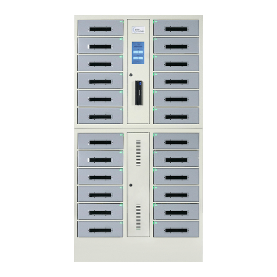
- Page 3 Product Information The SC-LOCKER-24 is designed to charge and secure up to 24 Chromebooks, Laptops or tablets. Specifications: Model SC-LOCKER-24 68.5 (H) x 35.5 (W) x 18.5 (D) Inch Exterior Dimensions 1740 (H) x 902 (W) x 470 (D) Inch 4.5 (H) x 12.4 (W) x 18.5 (D) Bay Dimensions 114 (H) x 315 (W) x 470 (D)
- Page 4 Product Information The CSC-LOCKER-8 is designed to charge, secure & sanitize up to 8 Chromebooks, Laptops, mobile or tablets. Specifications: Model CSC-LOCKER-8 Inch 68.5 (H) x 35.5 (W) x 18.5 (D) Exterior Dimensions 1740 (H) x 902 (W) x 470 (D) Inch 4.75 (H) x 11.5 (W) x 15 (D) Bay Dimensions...
- Page 5 Product Information The CSC-LOCKER-16 is designed to charge, secure & sanitize up to 16 Chromebooks, Laptops, mobile or tablets. Specifications: Model CSC-LOCKER-16 Inch 68.5 (H) x 35.5 (W) x 18.5 (D) Exterior Dimensions 1740 (H) x 902 (W) x 470 (D) Inch 4.75 (H) x 11.5 (W) x 15 (D) Bay Dimensions...
- Page 6 Product Information This manual covers the following models and part numbers. The manual is based upon the North American 110V product offering. Refer to the part numbers below and cord end diagrams for your specific region. MODEL# SC/CSC-LOCKER DESCRIPTION SC-LOCKER-12, 12 Bay Charging Locker With RFID Lock& Contact-Less Access - AC-Locker-12 110V NA (Legacy Number) LKR-SC-B12R-D...
- Page 7 Product Information The AC-Locker has been engineered to charge all connected devices from a single 15 A AC circuit. Power Cords and Sockets for Specific Region: US / Canada Power Cord Plug Socket United Kingdom Socket Power Cord Plug European Power Cord Plug Socket Australian...
- Page 8 Removing From Box Step-1: Remove the strapping with scissors or Step-2: Lift and Remove the top wood sheet, plier cutters. Do not use a box cutter. top cardboard lid and foam. Then remove corrugated cardboard from inner sides. Step-3: With the help of an assistant, gently lift Step-4: Remove all other packaging and the main box up and out of the way.
- Page 9 Product Information The SC-LOCKER-12 is designed to charge and secure up to 12 Chromebooks, Laptops or tablets. The assembly process is the same for single and double wide models. NOTE: Please review this guide before installing devices and to learn how to safely use your cart. Upper Access Door Upper Locker Touch Screen Display...
- Page 10 Product Information • Two AC outlets, up to 100 W power adapter on 12 Bay up to 60 W adapter on 24 Bay. Two USB charging ports, up to 2.4 A each. • Maintenance-free locks powered by the internal power supply. Individual Locker Individual Locker Power Module (2 USB +...
- Page 11 Product Information • The AC-Locker has been engineered to charge all connected devices from a single 15 A AC circuit. • Maintenance-free locks powered by the internal power supply Upper Mounting Bracket Handles Power Cord Middle Mounting Brackets Rear View of Cart 42035 Zevo Drive Temecula, CA 92590 | 888-650-4488 | www.powertechnologies.com PT-AC/SC/CSC-Locker Manual_Rev2023-11...
- Page 12 Assembly ASSEMBLY UP DEVICE : Step-1: On the Lower Cabinet, find and remove the keys attached to the power cord. Keys Step-2: On the Upper Cabinet, insert key into Access Door Lock and open door. Keys 42035 Zevo Drive Temecula, CA 92590 | 888-650-4488 | www.powertechnologies.com PT-AC/SC/CSC-Locker Manual_Rev2023-11...
- Page 13 Assembly Step-3: Press down on the uppermost top release lever for Bay #1. A Hex wrench and screen protecting film are located inside. Step-4: Locate the plastic bag containing the (1) Upper Mounting Bracket and (2) Middle Mounting Brackets Upper Mounting Bracket Middle Mounting Brackets 42035 Zevo Drive Temecula, CA 92590 | 888-650-4488 | www.powertechnologies.com PT-AC/SC/CSC-Locker Manual_Rev2023-11...
- Page 14 Assembly Step-5: Using the Hex wrench, remove the (3) Hex bolts from the top, back edge of the Upper Cabinet. Screw Step-6: With the Upper Mounting Bracket in hand, align the 3 round holes with the Upper Cabinet holes, making sure the slotted edge protrudes outward. Then, using the Hex wrench, install and tighten the (3) Hex bolts.
- Page 15 Assembly Step-7: On the Lower Cabinet, locate the Hex bolt from the front edge. Step-8: Using the Hex wrench, remove the Hex bolt from the front edge of the Lower Cabinet and set aside. IMPORTANT Do Not Discard the bolt. Screw 42035 Zevo Drive Temecula, CA 92590 | 888-650-4488 | www.powertechnologies.com PT-AC/SC/CSC-Locker Manual_Rev2023-11...
- Page 16 Assembly Step-9: Using the side handles, carefully lift the Upper Cabinet on top of the Lower Cabinet. For your safety, always move these pieces with the help of 1 or 2 assistants. 42035 Zevo Drive Temecula, CA 92590 | 888-650-4488 | www.powertechnologies.com PT-AC/SC/CSC-Locker Manual_Rev2023-11...
- Page 17 Assembly Step-10: On the Upper Cabinet, insert key into Access Door Lock and open door Step-11: Using the Hex bolt from step 8, secure both Cabinets together by inserting it into the Lower Cabinet threaded hole at the bottom, then tightening it using the Hex wrench. 42035 Zevo Drive Temecula, CA 92590 | 888-650-4488 | www.powertechnologies.com PT-AC/SC/CSC-Locker Manual_Rev2023-11...
- Page 18 Assembly Step-12: Working in the back, use the Hex wrench to remove the (4) Hex bolts from the middle left and middle right edges. 42035 Zevo Drive Temecula, CA 92590 | 888-650-4488 | www.powertechnologies.com PT-AC/SC/CSC-Locker Manual_Rev2023-11...
- Page 19 Assembly Step-13: With (1) Middle Mounting Bracket in hand, align the 2 narrow holes with the holes in the cabinets, making sure the slotted edge protrudes outward. Then, using the Hex wrench, install and tighten the (2) Hex bolts. Middle Mounting Brackets Step-14: Working on the opposite side, align the other (1) Middle Mounting Bracket, then install and tighten the (2) Hex bolts.
- Page 20 Setting Up Cables Step-1: Open both the Upper and Lower Access Panel doors with the key. Keys Step-2: Locate the Upper Data Connection Cable in the Upper Cabinet; It has a white, 4-pin connector (Molex style). Push the cable through the pass-through hole next to the black box. 42035 Zevo Drive Temecula, CA 92590 | 888-650-4488 | www.powertechnologies.com PT-AC/SC/CSC-Locker Manual_Rev2023-11...
- Page 21 Setting Up Cables Step-3: Locate the Lower Data Connection Cable in the Lower Cabinet. Step-4: Connect the Upper AND Lower Data Connection Cables together until clasp locks. 42035 Zevo Drive Temecula, CA 92590 | 888-650-4488 | www.powertechnologies.com PT-AC/SC/CSC-Locker Manual_Rev2023-11...
- Page 22 Setting Up Cables Step-5: In the Lower Cabinet, locate both the Power Strip Plug and the Power Input Plug. 42035 Zevo Drive Temecula, CA 92590 | 888-650-4488 | www.powertechnologies.com PT-AC/SC/CSC-Locker Manual_Rev2023-11...
- Page 23 Setting Up Cables Step-6: In the Upper Cabinet, locate the Power Supply; Its a black box with open electrical outlets. Step-7: One at a time, feed the Power Input Plug, then the Power Strip Plug through the pass- through hole located near the back. 42035 Zevo Drive Temecula, CA 92590 | 888-650-4488 | www.powertechnologies.com PT-AC/SC/CSC-Locker Manual_Rev2023-11...
- Page 24 Setting Up Cables Step-8: Plug both the Power Input Plug AND Power Strip Plug into the Power Supply. Step-9: Plug in the locker into an electrical outlet. 42035 Zevo Drive Temecula, CA 92590 | 888-650-4488 | www.powertechnologies.com PT-AC/SC/CSC-Locker Manual_Rev2023-11...
- Page 25 Mounting To Wall Step-1: Position your Locker so that wall studs or heavy duty wall anchors are accessible, as well as an electrical outlet. Step-2: Ensure the Upper Mounting bracket and both Middle Mounting Brackets are affixed to either wall studs or heavy duty wall anchors. 42035 Zevo Drive Temecula, CA 92590 | 888-650-4488 | www.powertechnologies.com PT-AC/SC/CSC-Locker Manual_Rev2023-11...
- Page 26 Safety Instructions Caution Danger THIS IS NOT A TOY. Notice Warning ALWAYS FOLLOW SAFETY INSTRUCTIONS. DO NOT place liquids on Don’t connect the cart with Important broken electrical components. or near the cabinet. THE ELECTRICAL SYSTEM IS DESIGNED TO HANDLE A MAXIMUM OF 1400 WATTS per side. If wattage exceeds 1400W at one time, charging system may not operate correctly.
- Page 27 Troubleshooting Trouble How to check Where to check The power is out and I need Open the Upper and Lower access Access Door Lock with key. Then, Push down on each Release lever to open Bays A User no longer remembers •...
- Page 28 Further Information For further information on this product and others, contact Power Technologies at. Power Technologies 42035 Zevo Dr Temecula, CA 92590+ 888.650.4488 support@powertechnologies.com www.powertechnologies.com 42035 Zevo Drive Temecula, CA 92590 | 888-650-4488 | www.powertechnologies.com PT-AC/SC/CSC-Locker Manual_Rev2023-11...
Need help?
Do you have a question about the AC-LOCKER Series and is the answer not in the manual?
Questions and answers