Hubbell CX Series Installation Instructions Manual
Lighting control panel 4 and 8
Hide thumbs
Also See for CX Series:
- User manual (22 pages) ,
- Installation instructions manual (11 pages)
Table of Contents
Advertisement
Quick Links
PRECAUTIONS
• READ AND FOLLOW ALL SAFETY INSTRUCTIONS.
• CAUTION: USE COPPER CONDUCTOR ONLY
• CAUTION: RISK OF ELECTRICAL SHOCK. To prevent electrical shock, turn off power at the circuit breaker before installing or servicing unit. Never wire
energized electrical components
• NOTE: For installation by licensed electrician in accordance with the National and/or Electrical Codes and the following instructions
• NOTE: Do not install if the product appears to be damaged. Be sure to read and understand all instructions before installing or servicing unit
• Run low voltage wiring with line voltage wiring in their respective compartments
• For indoor use only. Do not use outdoors unless all environmental requirements are met
• Do not mount near gas or electric heater
• Disconnect switch or a circuit breaker must be provided and marked as the disconnecting device
• The use of accessory equipment not recommended by the manufacturer may cause an unsafe condition
• Confirm that device ratings are suitable for the application prior to installation
• No user serviceable parts contained inside unit. Refer all service related questions to the factory
• All servicing shall be performed by qualified service personnel
• Equipment should be mounted in locations and at heights where it will not readily be subjected to tampering by unauthorized personnel
• Use only approved materials and components (i.e. twist on connectors, electrical box, etc.) as appropriate for installation
• If the equipment is used in a manner not specified by the manufacturer, the protection provided by the equipment may be impaired
• Do not use this equipment for other than intended use
• If any Emergency Circuits are fed or controlled from this panel, it must be located electrically where fed from a UPS, generator, or other guaranteed
source of power during emergency and power outage situations
• The CX panel enclosure and door are a complete assembly. Doors are not purchased separately
• SAVE THESE INSTRUCTIONS!
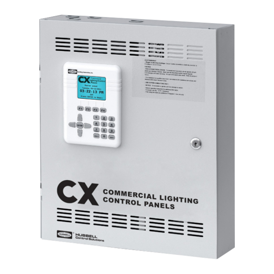
DESCRIPTION
The CX Lighting Control Panels are lighting control systems designed to control lighting loads as well as motor loads up to 2 HP. The system includes an
enclosure, power supply and or transformer, motherboard with Class 2 I/O user interface, and relay cards to control loads. The relay card is an open-type
accessory intended for installation inside the panel.
PRODUCT CONFIGURATION
MODEL
SPACES
INPUT VOLTAGE
CX
04
4 relay spaces
2
120/277VAC
(Stand Alone
version only)
08
8 relay spaces
3
120/347VAC
Examples: CX082S083LM - CX8 Relay Panel, 120-277VAC universal input, with 8 30A latching relays installed in NEMA 1 surface mount Master panel
RELAY MODEL
RELAY TYPE
CXR
2N
3L
3LEM*
TN
TC*
Copyright © 2019 Hubbell Control Solutions, a division of Hubbell Lighting, Inc. All rights reserved. All product and company names, logos and product
identifiers are trademarks ™ or registered trademarks ® of Hubbell Lighting, Inc. or their respective owners. Use of them does not necessarily imply any
ENCLOSURE
S
NEMA 1 Enclosure
00
04
08
1-Pole, Electrically Held, N.O.,120/277VAC
1-Pole, Latching,120/277/347VAC
1-Pole, Latching,120/277/347VAC
2-Pole, Electrically Held, N.O., 208/240/480VAC
2-Pole, Electrically Held, N.C., 208/240/480VAC
701 Millennium Blvd. | Greenville, SC 29607 | (864) 678-1000 | (866) 898-0131 - fax www.hubbellcontrolsolutions.com
affiliation with or endorsement by such respective owners.
Lighting Control Panel 4 and 8
INSTALLATION INSTRUCTIONS
RELAY QUANTITY
RELAY TYPE
No relays included
SP
Space Only
(Required SP Relay Type)
4 relays installed
2N
1-Pole elect. held N.O.
(fully populated)
relays (CXR2N)
3N
8 relays installed
1-Pole latching relays
(fully populated)
(CXR3L)
TN
2-Pole elect. held N.O.
relays (CXRTN)
OPTIONS
N
Stand-alone (4 Relay Panel
is neither a Master or
Secondary Panel
M
Master (available in CX08)
S
Secondary (available in CX08)
72-00445D
3300B 051619
Advertisement
Table of Contents

Related Manuals for Hubbell CX Series


Summary of Contents for Hubbell CX Series
- Page 1 Copyright © 2019 Hubbell Control Solutions, a division of Hubbell Lighting, Inc. All rights reserved. All product and company names, logos and product identifiers are trademarks ™ or registered trademarks ® of Hubbell Lighting, Inc. or their respective owners. Use of them does not necessarily imply any 3300B 051619 affiliation with or endorsement by such respective owners.
- Page 2 Copyright © 2019 Hubbell Control Solutions, a division of Hubbell Lighting, Inc. All rights reserved. All product and company names, logos and product identifiers are trademarks ™ or registered trademarks ® of Hubbell Lighting, Inc. or their respective owners. Use of them does not necessarily imply any 3300B 051619 affiliation with or endorsement by such respective owners.
-
Page 3: Installation Preparation
Copyright © 2019 Hubbell Control Solutions, a division of Hubbell Lighting, Inc. All rights reserved. All product and company names, logos and product identifiers are trademarks ™ or registered trademarks ® of Hubbell Lighting, Inc. or their respective owners. Use of them does not necessarily imply any 3300B 051619 affiliation with or endorsement by such respective owners. - Page 4 Copyright © 2019 Hubbell Control Solutions, a division of Hubbell Lighting, Inc. All rights reserved. All product and company names, logos and product identifiers are trademarks ™ or registered trademarks ® of Hubbell Lighting, Inc. or their respective owners. Use of them does not necessarily imply any 3300B 051619 affiliation with or endorsement by such respective owners.
-
Page 5: Connecting Panel Power
Copyright © 2019 Hubbell Control Solutions, a division of Hubbell Lighting, Inc. All rights reserved. All product and company names, logos and product identifiers are trademarks ™ or registered trademarks ® of Hubbell Lighting, Inc. or their respective owners. Use of them does not necessarily imply any 3300B 051619 affiliation with or endorsement by such respective owners. -
Page 6: Connecting Lighting Loads
Copyright © 2019 Hubbell Control Solutions, a division of Hubbell Lighting, Inc. All rights reserved. All product and company names, logos and product identifiers are trademarks ™ or registered trademarks ® of Hubbell Lighting, Inc. or their respective owners. Use of them does not necessarily imply any 3300B 051619 affiliation with or endorsement by such respective owners. - Page 7 Copyright © 2019 Hubbell Control Solutions, a division of Hubbell Lighting, Inc. All rights reserved. All product and company names, logos and product identifiers are trademarks ™ or registered trademarks ® of Hubbell Lighting, Inc. or their respective owners. Use of them does not necessarily imply any 3300B 051619 affiliation with or endorsement by such respective owners.
- Page 8 Copyright © 2019 Hubbell Control Solutions, a division of Hubbell Lighting, Inc. All rights reserved. All product and company names, logos and product identifiers are trademarks ™ or registered trademarks ® of Hubbell Lighting, Inc. or their respective owners. Use of them does not necessarily imply any 3300B 051619 affiliation with or endorsement by such respective owners.
-
Page 9: Operating Panel
Copyright © 2019 Hubbell Control Solutions, a division of Hubbell Lighting, Inc. All rights reserved. All product and company names, logos and product identifiers are trademarks ™ or registered trademarks ® of Hubbell Lighting, Inc. or their respective owners. Use of them does not necessarily imply any 3300B 051619 affiliation with or endorsement by such respective owners. - Page 10 Copyright © 2019 Hubbell Control Solutions, a division of Hubbell Lighting, Inc. All rights reserved. All product and company names, logos and product identifiers are trademarks ™ or registered trademarks ® of Hubbell Lighting, Inc. or their respective owners. Use of them does not necessarily imply any 3300B 051619 affiliation with or endorsement by such respective owners.
Need help?
Do you have a question about the CX Series and is the answer not in the manual?
Questions and answers