Table of Contents
Advertisement
Quick Links
Advertisement
Table of Contents

Related Manuals for smart-e VHX-7000-J

Summary of Contents for smart-e VHX-7000-J
-
Page 2: Table Of Contents
6.1 6U Rack Mounting................4 6.2 1U Rack Mounting................6 7. Web GUI User Guide................7 7.1 Preparation before Entering the System........7 7.2 Functions and Operation..............15 8. Application Example................27 Copyright 2023 Smart-e (UK) Ltd e&oe... -
Page 3: Introduction
④ 1 ⅹ 6-pin 3.81mm Phoenix Connector (Male) ⑤ 2 ⅹ Mounting Ears ⑥ 4 ⅹ Machine Screws (KM3*6) ⑦ 1 ⅹ 12V/1A Locking Power Adaptor ⑧ 1 ⅹ User Manual VHX-7000-J Controller User Manual V2.0 Page 1 / 29 © 2024 Smart-e (UK) Ltd... -
Page 4: Specifications
-20°C ~ 60°C / -4°F ~ 140°F Relative Humidity 20~90% RH (non-condensing) 5. Operation Controls and Functions 5.1 Front Panel P OWE R S TATUS RE S E T VHX-7000-J Controller User Manual V2.0 Page 2 / 29 © 2024 Smart-e (UK) Ltd... -
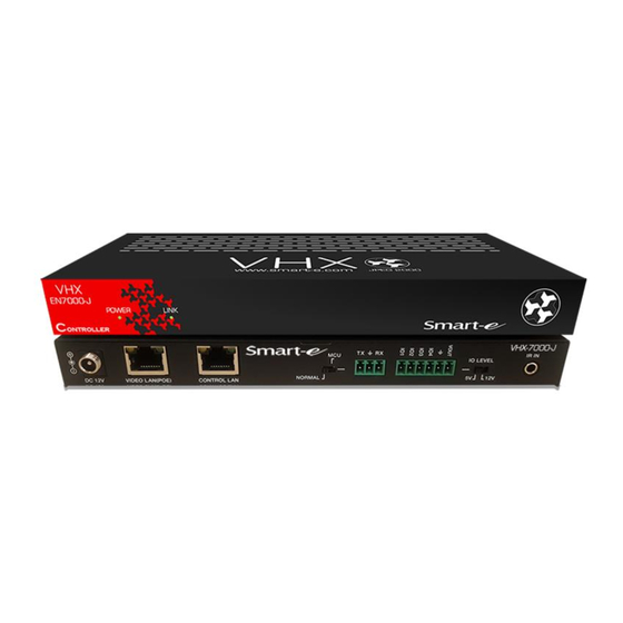
Page 5: Rear Panel
Switch to left: 5V I/O level output, VOUT is 5V. Switch to Switch right: 12V I/O level output, VOUT is 12V. 12V IR signal input port. IR IN VHX-7000-J Controller User Manual V2.0 Page 3 / 29 © 2024 Smart-e (UK) Ltd... -
Page 6: Ir Pin Definition
6U rack sale). The mounting steps are as follows: Step 1: Use included screws to fix two mounting ears on the Controller, as shown in the figure below: VHX-7000-J Controller User Manual V2.0 Page 4 / 29 © 2024 Smart-e (UK) Ltd... - Page 7 Step 3: Use screws to fix mounting ears on the rack to complete the mounting, as shown in the figure below: VHX-7000-J Controller User Manual V2.0 Page 5 / 29...
-
Page 8: Rack Mounting
Step 3: Fasten screws between two 1U rack panels, so that four Controllers are mounted in a 1U rack, as shown in the figure below: VHX-7000-J Controller User Manual V2.0 Page 6 / 29 © 2024 Smart-e (UK) Ltd... -
Page 9: Web Gui User Guide
Then click “Login” to enter the password modification interface, as shown below. Please set a six-digit password using letters or numbers, then use the new password to login the Web GUI. VHX-7000-J Controller User Manual V2.0 Page 7 / 29 © 2024 Smart-e (UK) Ltd... - Page 10 “Next” button to go to the next step. The next page gives you 3 options to set up the Video LAN: 1 – Automatic using the controller VHX-7000-J; 2 – HDCP option using a separate server or 3 – Static mode for manual IP address setup.
- Page 11 Controller automatically using the following connection method: Click the “Next” button and wait for the completion to enter the interface as shown in the figure below. VHX-7000-J Controller User Manual V2.0 Page 9 / 29 © 2024 Smart-e (UK) Ltd...
- Page 12 If you want to change the IP mode of Video LAN, you can click “Search Device Via Wizard” on the Device interface and switch back to the IP mode select interface. VHX-7000-J Controller User Manual V2.0 Page 10 / 29...
- Page 13 Select “DHCP Mode” on the interface shown below and click “Next”. The rest of the steps are the same as the Option 1 operation. Video Wall VHX-7000-J Controller User Manual V2.0 Page 11 / 29 © 2023 Smart-e (UK) Ltd...
- Page 14 O UT HDM I O UT 1G Ethernet Switch Select “Static IP mode by manual settings” on the interface shown below and click “Next”. Video Wall VHX-7000-J Controller User Manual V2.0 Page 12 / 29 © 2023 Smart-e (UK) Ltd...
- Page 15 “Next” button to enter the interface as shown in the figure below: The rest of the steps are the same as the Option 1 operation. VHX-7000-J Controller User Manual V2.0 Page 13 / 38 © 2023 Smart-e (UK) Ltd...
-
Page 16: Functions And Operation
Encoder/Decoder after clicking the drop-down icon on the left side of ID. Note: The controller can simultaneously control two types of Encoders and Decoders (distinguished by Gen 1/2 ) in one system. VHX-7000-J Controller User Manual V2.0 Page 14 / 38... - Page 17 Encoder HDMI output and Decoder audio output. Network Settings ① IP Mode: Click the drop-down menu to set the IP mode (Static/DHCP). ② IP Address: The IP address of the Encoder. VHX-7000-J Controller User Manual V2.0 Page 15 / 38 © 2023 Smart-e (UK) Ltd...
- Page 18 ④ Network Interface Usage: Click the drop-down menu to set the network port (Fiber/Copper). Note: Only Encoders that integrate Copper and Fiber ports can perform this setting. VHX-7000-J Controller User Manual V2.0 Page 16 / 38 © 2023 Smart-e (UK) Ltd...
- Page 19 ⑥ IO 2: Click the drop-down menu to set the IO 2 level (Low/High). ⑦ Relay 1: Click the drop-down menu to select Open/Close Relay 1. ⑧ Relay 2: Click the drop-down menu to select Open/Close Relay 2. VHX-7000-J Controller User Manual V2.0 Page 17 / 38...
- Page 20 Remove: Click the Remove button to remove the Encoder from the system. Remove All: Click this button to remove all Encoders from the system. Factory Reset: Click this button to restore the Encoder to factory settings. VHX-7000-J Controller User Manual V2.0 Page 18 / 38...
- Page 21 270° to rotate the image or select Flip Horizontal/Vertical to flip the image. ④ Scaling: Click the drop-down menu to set the video output scaling resolution. VHX-7000-J Controller User Manual V2.0 Page 19 / 38 © 2023 Smart-e (UK) Ltd...
- Page 22 Example: follow steps below to change the video routing of Decoder 004 to be from Encoder 009. Step 1. Click the drop-down menu of Video to select “Encoder 009”. VHX-7000-J Controller User Manual V2.0 Page 20 / 38 © 2023 Smart-e (UK) Ltd...
- Page 23 (1) If the IP mode is set to “Static”, you can manually set the IP Address, Subnet Mask and Gateway as required. Then click “Apply”, the Decoder will immediately reboot to take effect. VHX-7000-J Controller User Manual V2.0 Page 21 / 38...
- Page 24 Decoder. Note: The settings of “Sink Capability”, “Audio Return Path” and “eARC Downgrade To ARC” are available only for Decoders that support ARC/eARC. VHX-7000-J Controller User Manual V2.0 Page 22 / 38 © 2023 Smart-e (UK) Ltd...
- Page 25 ⑤ IO 2 Direction: Click the drop-down menu to set the IO 2 direction (Input/ Output). ⑥ IO 2: Click the drop-down menu to set the IO 2 level (Low/High). VHX-7000-J Controller User Manual V2.0 Page 23 / 38 © 2023 Smart-e (UK) Ltd...
- Page 26 Wizard to set up the system. ③ Add All Into System: Click this button to add all searched devices into the system, then the devices will be listed on the Encoder/Decoder list. VHX-7000-J Controller User Manual V2.0 Page 24 / 38...
- Page 27 Decoders 004~008 output the signal from Encoder 006, because these Encoders and Decoders belong to the same type. VHX-7000-J Controller User Manual V2.0 Page 25 / 38 © 2023 Smart-e (UK) Ltd...
- Page 28 Corresponding Relationship Query Double-click the preview image of Decoder to check the Video/Audio/IR/ RS-232/USB corresponding relationship between the Encoder and Decoder. ■ Video Wall Page VHX-7000-J Controller User Manual V2.0 Page 26 / 38 © 2023 Smart-e (UK) Ltd...
-
Page 29: Application Example
Click each screen to select the corresponding Decoder device, then click “Apply” to take effect. Notes: A Decoder can only be assigned to one video wall. VHX-7000-J Controller User Manual V2.0 Page 27 / 38 © 2023 Smart-e (UK) Ltd... - Page 30 Image Height. Finally, click “Apply” to adjust the border of each Decoder, or click “Apply All” to adjust the borders of all Decoders. Note: The Base value cannot be more than 2 times the Image value. VHX-7000-J Controller User Manual V2.0 Page 28 / 38...
- Page 31 If you want to delete a video wall, just select the video wall on the “Video Wall List”, then click “Remove”. A prompt window will pop up and you can delete it after clicking “Yes”. VHX-7000-J Controller User Manual V2.0 Page 29 / 38...
- Page 32 Step 1: Click “Create”, a pop-up window will be shown as below. Step 2: Input the Username, User Password and Confirm Password. Then click “Go” to create the User. VHX-7000-J Controller User Manual V2.0 Page 30 / 38 © 2023 Smart-e (UK) Ltd...
- Page 33 User. If you want to login with the new User, just click the logout icon at the upper right corner of this page to log out, and then login with the new username and password. VHX-7000-J Controller User Manual V2.0 Page 31 / 38...
- Page 34 ① General: The general settings of the Controller. You can check the Controller Version, GUI Version and Domain Name. In addition, you can click the drop-down menu to set the RS-232 BaudRate and HTTPS. VHX-7000-J Controller User Manual V2.0 Page 32 / 38...
- Page 35 “Update” to apply the picture for a single Decoder. Note: The jpg picture must be greater than 4kB, less than or equal to 512kB, and the resolution of the picture must be less than or equal to 1920x1080. VHX-7000-J Controller User Manual V2.0 Page 33 / 38...
- Page 36 ■ Password Update Page On this page, you can change the password by inputting the New Password and Confirm Password, and then clicking “Apply” to take effect. VHX-7000-J Controller User Manual V2.0 Page 34 / 38 © 2023 Smart-e (UK) Ltd...
- Page 37 HDM I OUT D C 12V IR IN IR OUT USB HOS T R S-2 3 2 AUDIO HDM I OUT HDM I IN Video Wall VHX-7000-J Controller User Manual V2.0 Page 35 / 38 © 2023 Smart-e (UK) Ltd...
- Page 38 HDM I OUT D C 12V IR IN IR OUT USB HOS T R S-2 3 2 AUDIO HDM I OUT HDM I IN Video Wall VHX-7000-J Controller User Manual V2.0 Page 36 / 38 © 2023 Smart-e (UK) Ltd...
- Page 39 HDM I OUT D C 12V IR IN IR OUT USB HOS T R S-2 3 2 AUDIO HDM I OUT HDM I IN Video Wall VHX-7000-J Controller User Manual V2.0 Page 37 / 38 © 2023 Smart-e (UK) Ltd...
- Page 40 Controller automatically (Default). (6) When the Network Switch does not support POE, the Encoder, Decoder and Controller Box should be powered by DC power adapter VHX-7000-J Controller User Manual V2.0 Page 38 / 38 © 2023 Smart-e (UK) Ltd...
Need help?
Do you have a question about the VHX-7000-J and is the answer not in the manual?
Questions and answers