Advertisement
Quick Links
Advertisement

Related Manuals for hernest HEFTSB-0005


Summary of Contents for hernest HEFTSB-0005
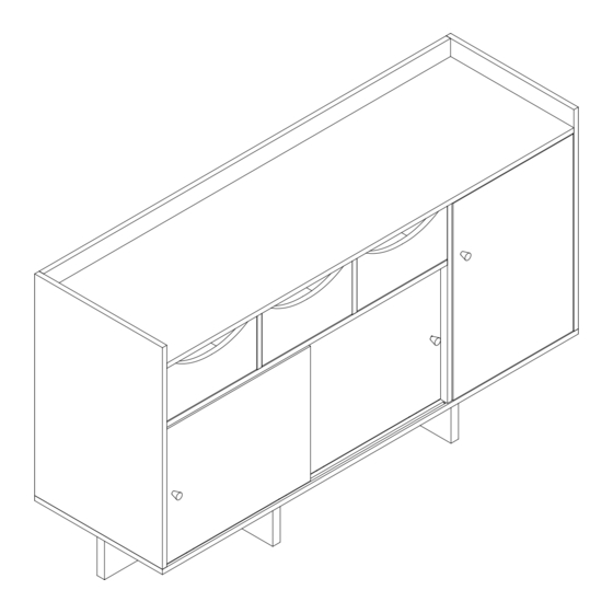
- Page 1 HERNEST ASSEMBLY INSTRUCTIONS HEFTSB-0005...
- Page 2 HERNEST ASSEMBLY INSTRUCTIONS Notice: 1.Follow the installation instructions. Please con fi rm all accessories are preset before installation. 2.Do not fully tighten the screws during initial assembly.Fully tighten screws only once all pieces which are correctly assembled. 3.If you encounter any problems during installation,please contact our customer service.
- Page 3 HERNEST ASSEMBLY INSTRUCTIONS Item Item Reference Image Qty. Reference Image Qty. x12+1 Ø3.5x12mm x16+1 x16+1 Ø3x14mm x14+1 Ø5x45mm Ø6x30mm Ø3x12mm 15x390mm...
- Page 4 HERNEST ASSEMBLY INSTRUCTIONS Item Item Reference Image Qty. Reference Image Qty.
- Page 5 HERNEST ASSEMBLY INSTRUCTIONS Item Item Reference Image Qty. Reference Image Qty.
- Page 6 HERNEST ASSEMBLY INSTRUCTIONS Item Item Reference Image Qty. Reference Image Qty.
- Page 7 HERNEST ASSEMBLY INSTRUCTIONS A 12pcs 3pcs...
- Page 8 HERNEST ASSEMBLY INSTRUCTIONS 12pcs 3pcs 3pcs Cam Lock Fastening System 3pcs...
- Page 9 HERNEST ASSEMBLY INSTRUCTIONS 12pcs 3pcs 6pcs...
- Page 10 HERNEST ASSEMBLY INSTRUCTIONS 4pcs 4pcs 2pcs A 2pcs...
- Page 11 HERNEST ASSEMBLY INSTRUCTIONS C 2pcs B 2pcs Cam Lock Fastening System...
- Page 12 HERNEST ASSEMBLY INSTRUCTIONS 6pcs 3pcs O 2pcs 5pcs...
- Page 13 HERNEST ASSEMBLY INSTRUCTIONS A 2pcs 3pcs 2pcs Cam Lock Fastening System...
- Page 14 HERNEST ASSEMBLY INSTRUCTIONS C 6pcs B 6pcs Cam Lock Fastening System...
- Page 15 HERNEST ASSEMBLY INSTRUCTIONS 5pcs A 3pcs...
- Page 16 HERNEST ASSEMBLY INSTRUCTIONS C 5pcs 4pcs Cam Lock Fastening System...
- Page 17 HERNEST ASSEMBLY INSTRUCTIONS B 2pcs 3pcs Cam Lock Fastening System...
- Page 18 HERNEST ASSEMBLY INSTRUCTIONS B 2pcs Cam Lock Fastening System...
- Page 19 HERNEST ASSEMBLY INSTRUCTIONS 2pcs...
- Page 20 HERNEST ASSEMBLY INSTRUCTIONS 8pcs 6pcs 6pcs...
- Page 21 HERNEST ASSEMBLY INSTRUCTIONS 2pcs 2pcs 4pcs 2pcs...
- Page 22 HERNEST ASSEMBLY INSTRUCTIONS 8pcs 8pcs Cam Lock Fastening System...
- Page 23 HERNEST ASSEMBLY INSTRUCTIONS T 4pcs...
- Page 24 HERNEST ASSEMBLY INSTRUCTIONS 16pcs L 16pcs...
- Page 25 HERNEST ASSEMBLY INSTRUCTIONS 8pcs...
- Page 26 HERNEST ASSEMBLY INSTRUCTIONS...
- Page 27 HERNEST ASSEMBLY INSTRUCTIONS 4pcs 2pcs 2pcs 2pcs...
- Page 28 HERNEST ASSEMBLY INSTRUCTIONS 8pcs Etape 1 Etape 2 Etape 5 Etape 4 Etape 3...
- Page 29 HERNEST ASSEMBLY INSTRUCTIONS...
- Page 30 HERNEST ASSEMBLY INSTRUCTIONS Push the button to relief the door pin. Important: If the door not firm, please screw the middle screw to adjust the height of wheel as shown. down...
- Page 31 HERNEST ASSEMBLY INSTRUCTIONS...
- Page 32 HERNEST ASSEMBLY INSTRUCTIONS 2pcs 2pcs 2pcs 2pcs ATTENTION: For safety and stability, we suggest you have to secure the anti tip accessories to the wall to prevent tipping, injury, and property damage. WALL WALL (1) WALL drilling hole Ø6x30mm (2)...
Need help?
Do you have a question about the HEFTSB-0005 and is the answer not in the manual?
Questions and answers