Table of Contents
Advertisement
Advertisement
Table of Contents

Related Manuals for BILT HARD TGA-0251

Summary of Contents for BILT HARD TGA-0251
- Page 1 Inverter Generator TGA-0251...
-
Page 3: Table Of Contents
TABLE OF CONTENTS Introduction..........1 Maintenance ........15 Introduction..........1 Engine Maintenance.......15 Portable Power Generator.........1 Oil..........15 This Booklet..........1 Spark Plugs........15 Specifications........2 Air Filter..........16 Cleaning..........16 Manual Conventions........3 Clean the Spark Arrestor......16 Safety Rules..........4 Adjustments........17 Fuel Safety...........6 Maintenance Schedule.......17 Controls and Features......7 Generator Maintenance......17 Inverter ............7 Transportation and Storage....18 Parts Included..........7... -
Page 4: Introduction
TGA-0251... -
Page 5: Specifications
SPECIFICATIONS 120V AC, 60 Hz, 16.7 A, 1 Phase 12V DC, 8.3 A Output 2000 Running Watts 2500 Maximum Starting Watts Generator 120V 20A Duplex (5-20R) Receptacles 12V DC Automotive Displacement 80 cc Compression Ratio 9.1:1 Horizontal Single Cylinder Engine Type 4-stroke, OHV Cooling System Forced air cooled... -
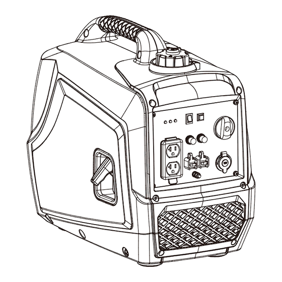
Page 11: Power Panel
ECONOMY RESET OVERLOAD OUTPUT CIRCUIT DC CIRCUIT BREAKER BREAKER 120V CAUTION:DO NOT disconnect parallel cables while generator is running PARALLEL OPERATING SYSTEM Fuel Valve Knob 120 Volt AC, 20 Amp Duplex (NEMA 5-20R) – May be used to supply electrical power for the operation of 120 Volt AC, 20 Amp, single phase 60 Hz electrical loads. -
Page 12: Assembly
Turn the knob from lock to open.Then remove the maintenance cover. Open 0.4L... -
Page 13: Add Fuel
Add fuel until reach the red line. Add fuel until reach the red line. -
Page 14: Operation
Do not use in rainy or wet conditions. Do not touch Using a generator indoors CAN KILL YOU IN MINUTES. bare wires or receptacles (outlets). Do not allow Generator exhaust contains carbon monoxide (CO). This children or non-qualified persons to operate. is a poison gas you cannot see or smell. -
Page 15: Before Starting The Generator
Before Starting the Generator 1. Verify that generator is outside on a dry, level surface with at least two feet of clearance on all sides. 2. To maximize safety, check that the generator is properly grounded. 3. Check there is sufficient level of oil in the crankcase. Add oil if necessary. -
Page 16: Connecting Electrical Devices
Connecting Electrical Devices When the rated wattage requirement of each electrical device has been determined, add these numbers to find the total rated wattage needed. If this number exceeds the rated wattage of the generator, DO NOT connect all these devices. Select a combination of electrical devices with a total rated wattage lower than or equal to the rated wattage of the generator. -
Page 17: Economy Control Switch
while operating with an output less than 75% of the rated watts of the generator. Allowing Economy Control Switch DC 12V Outlet (For charging ONLY) The 12V DC outlet can be used with the supplied charge cable and USB charger and other commercially available 12V DC automotive style plugs. -
Page 18: Maintenance
Open (not included) 0.4L... -
Page 19: Air Filter
Clean the Spark Arrestor 1. Allow the engine to cool completely before servicing the spark arrestor. 2. Remove the 6 screws holding the cover plate on the muffler side of the generator. 3. Remove the clamp(C) and cap(B) which retain the spark arrestor(A) to the muffler. Foam Element 4. -
Page 21: Transportation And Storage
TRANSPORTATION AND STORAGE Transporting the Generator To prevent fuel spillage when transporting, be sure to Store the generator upright in a cool and dry location, perform the following: away from sources of heat, open flames,sparks or 1. Tighten the fuel cap. pilot lights. -
Page 22: Troubleshooting
TROUBLESHOOTING Problem Cause Solution No fuel. Add fuel. Faulty spark plug. Clean and adjust spark plug or replace. Fill crankcase to the proper level. Low oil level. Place generator on a flat, level surface. Spark plug wire loose. Attach wire to spark plug. Engine will not start. -
Page 23: Parts Diagram
PARTS DIAGRAM... -
Page 24: Parts List
PARTS LIST Part Number Description Part Number Description 62.070100.00 Fuel Tank Cap 32.200203.00 Knob 63.070300.00 Fuel Filter, Wire Mesh 2.03.070 Retaining Ring, M6 32.200902.00 Spillway, Fuel Tank 32.200603.00 Rear Cover muffler sealing ring 1.818.0516 Screw M5 x 16 32.200602.01 Anechoic sponge, Rear Cover 32.071000.00 Fuel Tank,5.2L 32.200601.00... -
Page 25: Engine Parts Diagram
ENGINE PARTS DIAGRAM... -
Page 26: Engine Parts List
ENGINE PARTS LIST Part Number Description Part Number Description 1.5782.06100 Flange Bolt M6 x 100 45 32.130001.00 Insulator, Carburetor 1.6177.1.06 Flange Lock Nut M6 46 81.130003.00 Gasket, Carburetor 32.101000.00 Muffler Assembly 47 32.130000.00 Carburetor Assembly 81.100001.00 Gasket, Exhaust Pipe 48 81.130004.00 Gasket, Air Cleaner 32.030007.00 Cover, Crankcase...
Need help?
Do you have a question about the TGA-0251 and is the answer not in the manual?
Questions and answers
Can I just buy the crankshaft ?