Table of Contents
Advertisement
Quick Links
Advertisement
Table of Contents

Related Manuals for Haff & Schneider Rotoklick II


Summary of Contents for Haff & Schneider Rotoklick II
- Page 1 Operating Instructions - Translation- Please store for future use. Rotoklick II...
- Page 2 • the safety instructions • the maintenance of the device. Storage The Operating Instructions must always be kept in close vicinity of Rotoklick II for later reference. They should always be accessible. © 2024 Haff & Schneider GmbH & Co. OHG...
-
Page 3: Table Of Contents
Operating Instructions Rotoklick II Contents General notes ....................5 Observe the notes in the Operating Instructions ............5 Warranty and liability ..................... 5 Intended use ......................... 5 Field of application ......................6 Foreseeable misuse ...................... 6 Nameplate ........................6 Scope of delivery ......................6 Safety ......................... - Page 4 Storage ........................55 10.3 Disposal ........................55 Annex ....................... 56 11.1 List of part numbers ....................56 11.2 EU Declaration of Conformity ..................57 11.3 Rotoklick II - Dimension sheet ..................58 11.4 Rotoklick II - Component overview ................59...
-
Page 5: General Notes
General notes Observe the notes in the Operating Instructions For safe handling and trouble-free operation of Rotoklick II, the operating staff must be familiar with the basic safety instructions and safety regulations. These Operating Instructions include important information for safe and proper operation and handling of Rotoklick II and must be stored at the operation site. -
Page 6: Field Of Application
Operating Instructions Rotoklick II Field of application The use of Rotoklick II is only allowed in industrial or professional environments. Rotoklick II has been designed only for indoor applications. The mounting surface must be level and clean. Ambient temperature at the installation site: +5 to +40 °C Maximum humidity: Max. -
Page 7: Safety
Operating Instructions Rotoklick II Safety Presentation of safety instructions The safety instructions in these Operating Instructions are classified into general information, notes, cautions, warnings and dangers. The safety instructions used in these Operating Instructions are shown below by way of example to illustrate the types of the safety instructions and the respective hazard levels. -
Page 8: Informal Safety Measures
In addition to the Operating Instructions, the general local rules and regulations for accident prevention and environmental protection must be provided and complied with. Furthermore, the safety measures required for the machine in which Rotoklick II is incorporated must be observed. Always wear the personal protective equipment required for this machine. - Page 9 Operating Instructions Rotoklick II CAUTION Hazard generated by poor lighting The risk of accidents increases with poor lighting. → Select a lighting system of appropriate illuminance for the surrounding area. → Ensure unobstructed view of the machining process. NOTE Hazard generated by overloading Machine and device overloading can cause damage.
-
Page 10: Personal Protective Equipment
Operating Instructions Rotoklick II Personal protective equipment Pictogram Description Wear protective footwear ➔ Protective footwear will protect the feet against crushing, falling parts and slipping on slippery surfaces. Wear protective gloves ➔ Protective gloves are used to protect the hands against... -
Page 11: Qualification Level
Operating Instructions Rotoklick II Qualification level All maintenance, inspection and repair work may only be performed by persons complying with the qualification levels of the manufacturer. Qualification Definition of the qualification level level The operator must be instructed by the operating company in the... -
Page 12: Responsibilities For Activities
Operating Instructions Rotoklick II Responsibilities for activities Activity Qualification level Transport Non-specialists Assembly, installation Qualified staff Commissioning Qualified staff Use/operation Instructed operator Repair and maintenance Qualified staff Decommissioning, disassembly, Qualified staff disposal Time limits Specification Description Maximum uninterrupted operating time... -
Page 13: Working Area And Danger Zone
Operating Instructions Rotoklick II Working area and danger zone The danger zone must be entered for the following tasks: • Operation of machine and device (manual indexing) • Material feeding • Machine set-up • Installation of accessories • Cleaning •... -
Page 14: Description
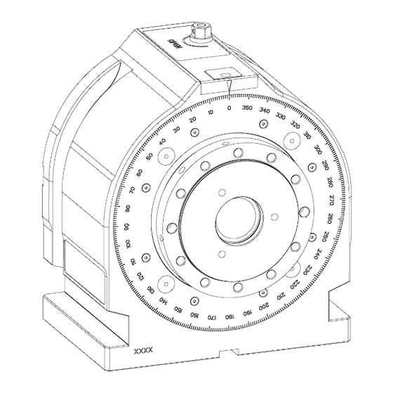
The front and the sides of the spindle (5) are provided with various tapped holes (7) and fittings that can be used to mount further optional devices. Rotoklick II is mounted and aligned on the table by means of the T-slots (9) and a shallow slot at the bottom side (8). -
Page 15: Technical Data
Operating Instructions Rotoklick II Technical data Item Value / range Length 204.5 mm Width 260 mm Height 290 mm Division 360 x 1° Standard center height 150 mm Center height with optional spacers 200 mm or 250 mm Mounting diameter (cyl.) Ø... -
Page 16: Commissioning
WARNING Hazard generated by interference with the machine spindle Since Rotoklick II is mounted in the working area of the machine, it can interfere with the machine spindle. → Always run in NC programs at reduced feedrate. → Approach Rotoklick II at reduced feedrate. - Page 17 Operating Instructions Rotoklick II CAUTION Cutting hazard Clamped tools or chips in the working area can cause cuts. → Before carrying out any work in the working area, remove any tools or chips. CAUTION Hazard generated by improper handling of assembly tools Risk of injury is generated when slipping off with the tool during assembly or disassembly work.
-
Page 18: Transport
Operating Instructions Rotoklick II Transport WARNING Hazard generated by components Falling components due to the use of inappropriate hoists and slings without sufficient load carrying capacity can cause severe injury or death. → Always use appropriate hoists and slings having sufficient load carrying capacity. -
Page 19: Transport Of Dividing Head
Operating Instructions Rotoklick II 5.1.1 Transport of dividing head Required tools / materials: • Crane • Round sling (min. load carrying capacity 50kg) Procedure: • Pull the round sling through the hollow spindle. • Hook the round sling into a hoist or crane designed for the lifting work to be carried out. -
Page 20: Transport Of Dividing Head Including Optional Equipment
Operating Instructions Rotoklick II 5.1.2 Transport of dividing head including optional equipment Required tools / materials: • Crane • Round sling (min. load carrying capacity 100kg) • 4 x eyebolts Procedure: • Screw the eyebolts (1) into the face of the base plate. -
Page 21: Attachment In The Working Area
Operating Instructions Rotoklick II Attachment in the working area 5.2.1 Upright attachment • Clamping directly on the machine table or pallet • Alignment by means of a sliding block in the 20H7 slot at the bottom side • Attachment to the provided clamping edge / T-slots on the machine table / pallet by... -
Page 22: Flat Attachment
Operating Instructions Rotoklick II 5.2.2 Flat attachment • Clamping directly on the machine table or pallet • Alignment by means of a sliding block in the 20H7 slot at the bottom side • Attachment to the provided clamping edge / T-slots on the machine table / pallet by... -
Page 23: Manual Indexing
Operating Instructions Rotoklick II Manual indexing WARNING Crushing hazard Crushing hazard is generated by moving between two movable components or between one moveable and one stationary component having flat, edgeless surfaces. → Secure loads with appropriate safeguarding devices. → The device must be used only by instructed staff. - Page 24 • Automatic locking is done in accurate 1° increments. Information A slight resistance is felt in the zero-degree position of Rotoklick II and serves as an aid to orientation. Information Depending on workpiece size and weight, it may be impossible to rotate the dividing head by mere muscular strength;...
-
Page 25: Cnc-Controlled Indexing
→ The device must be commissioned only by instructed and qualified staff. NOTE Notes on programming the feedrate: • Faults when locking Rotoklick II • Damage of the indexing tool Dwell should be used with certain types of control to ensure an accurate push-in... - Page 26 Operating Instructions Rotoklick II Information The cylindrical shank of the indexing tool fits any tool holder having a diameter of D = 20 mm. Description: During CNC-controlled indexing, the indexing process is carried out with the aid of an indexing tool. During this process, the indexing tool is pushed into the pick-up point and it turns the scale to the desired position at increments of max.
-
Page 27: Indexing Tool
Operating Instructions Rotoklick II Indexing tool CAUTION Caution The tappet of the indexing tool must face the dividing head! (max. angular deviation admitted: + 3°) Larger angular deviations must be compensated for: • either: Compensate by means of spindle orientation of the CNC unit. -
Page 28: Vertical Indexing Tool
Operating Instructions Rotoklick II 7.1.1 Vertical indexing tool Description The vertical indexing tool is used for machines with vertical spindle. When clamping the indexing tool, its clamping shank must be inserted into the holder until it has contact with the stop and then be tightened with the clamping bolt. Then the tool data must be entered into the control unit. -
Page 29: Horizontal Indexing Tool
Operating Instructions Rotoklick II 7.1.2 Horizontal indexing tool 1 Locating screw with predetermined breaking point Description The horizontal indexing tool is used for machines with horizontal spindle. For clamping, proceed in the same manner as when clamping the vertical indexing tool. -
Page 30: Predetermined Breaking Point On The Indexing Tool
Operating Instructions Rotoklick II 7.1.3 Predetermined breaking point on the indexing tool 1 Replacement screw 3 Dowel pin (stop) 2 Locating screw with predetermined breaking point... -
Page 31: Reference Point / Program Zero Point For Indexing Movement
Operating Instructions Rotoklick II 7.1.4 Reference point / program zero point for indexing movement 1 Dividing circle 4 Pick-up 1-4 2 Indexing tool 5 Program zero point 3 Reference point Procedure: • Enter the indexing tool data into the tool memory (L = tool length TL, R = 0). -
Page 32: Approach / Unlock
Operating Instructions Rotoklick II 7.1.5 Approach / unlock Procedure: • Approach the starting point G0 X0 Y0 Z160. • Check the position of the 1st pick-up point. • Check the starting angle on the scale. • Determine the coordinates by means of the angle calculator and approach them in the Y and Z axes (X = 0). -
Page 33: Indexing Movement / Rotation
Operating Instructions Rotoklick II 7.1.6 Indexing movement / rotation Procedure: • For programming a circular movement with the circle center Y0 and Z0, the rotary movement G2 is carried out. • Determine the coordinates of the pick-up point end position using the angle calculator. -
Page 34: Lock / Retract
Operating Instructions Rotoklick II 7.1.7 Lock / retract Procedure: • The indexing tool is retracted from the pick-up point. • Approach the starting point. -
Page 35: Use Of The Angle Calculator
Operating Instructions Rotoklick II Use of the angle calculator https://haff- For this product, further information is available. Scan the QR code or visit schneider.com/support/rotoklick-2/angle-calculator/. • Scan the QR code. • The angle calculator opens up. • Open the dropdown menu in the selection field "direction of rotation“ and select the desired mode. - Page 36 Operating Instructions Rotoklick II...
-
Page 37: Example 1: Rotary Movement From 0° To 90
Operating Instructions Rotoklick II 7.2.1 Example 1: Rotary movement from 0° to 90° • Entry: Starting angle = 0, target angle = 90... - Page 38 Operating Instructions Rotoklick II • Step 1: 1. The pick-up point travels from the starting point coordinates to the end point coordinates. • Press the button. • 1. The pick-up point turns to the end point coordinates. → 90° have been reached.
-
Page 39: Example 2: Rotary Movement From 0° To 120
Operating Instructions Rotoklick II 7.2.2 Example 2: Rotary movement from 0° to 120° Information Since the working area is + 45°, any rotary movement exceeding 90° must be carried out in two steps. • Entry: Starting angle = 0, target angle = 120... - Page 40 Operating Instructions Rotoklick II • Step 1: 1. The pick-up point travels from the starting point coordinates to the end point coordinates. • Press the "rotate" button.
- Page 41 Operating Instructions Rotoklick II • 1. The pick-up point turns to the end point coordinates. • Press the "next step" button. • 2. The pick-up point is selected.
- Page 42 Operating Instructions Rotoklick II • Press the "rotate" button. • 2. The pick-up point turns from the starting point coordinates to the end point coordinates. →120° have been reached.
-
Page 43: Programming Examples
N15 M30 Meaning N9101 (Macro indexing movement) N10 G93 X18 Y0 Z-140 (Abs. zero offset to the Rotoklick II axis) N11 G0 X0 Y0 Z160 (Starting position above Rotoklick II) N12 G1 Y-66.468 Z66.468 (Approach pick-up point 1) N14 G1 X-11.5 (Push-in / unlock) N15 G2 Y66.468 Z66.468 J0 K0 (Rotate from 0°... -
Page 44: Programming Example For Heidenhain Tnc 355
The zero point is the reference zero point (refer to the angle calculator). 0 BEGIN PGM 2802961 MM (Rotate Rotoklick II from 0° to 90°) 1 TOOL CALL 90 Z S 0.00 (Tool length in tool memory) Spindle stop position 3 CYCL DEF 7.0 NULLPUNKT... -
Page 45: Programming Example For Heidenhain Tnc 640
1 TOOL CALL 90 Z S 0.00 (Tool length in tool memory) Spindle stop position 3 CYCL DEF 7.0 NULLPUNKT (Zero offset in Rotoklick II axis) 4 CYCL DEF 7.1 X-18.000 5 CYCL DEF 7.2 Y+0.000 6 CYCL DEF 7.3 Z-140.000 7 L X+0.000 Y+0.000 R0 F9999... -
Page 46: Optional Equipment
Operating Instructions Rotoklick II Optional equipment WARNING Crushing hazard Crushing hazard is generated by moving between two movable components or between one moveable and one stationary component having flat, edgeless surfaces. → Secure loads with appropriate safeguarding devices. → The device must be used only by instructed staff. - Page 47 Operating Instructions Rotoklick II Rotoklick II can be expanded by additional optional equipment (e.g. lathe chuck, rocker, cube or traverse). Tailstocks or counter holders are used to support large workpieces. Furthermore, the counter holder prevents any bending of rocker, cube or traverse during the machining of large workpieces.
-
Page 48: Wedge-Shaped Clamping Elements For Radial Flange Connection
Operating Instructions Rotoklick II Wedge-shaped clamping elements for radial flange connection 1 Wedge-shaped clamping elements (4x) Description These wedge-shaped clamping elements enable various attachments to be mounted to Rotoklick II without any major effort. -
Page 49: Lathe Chuck
Operating Instructions Rotoklick II Lathe chuck Description The lathe chuck can be used with or without tailstock or counter holder. The jaw chuck enables all-around machining of round workpieces. Thanks to a hollow spindle, bars up to a diameter of D40 can be machined. -
Page 50: Rocker
Operating Instructions Rotoklick II Rocker Description The rocker features an asymmetrical design. High rigidity is achieved when the workpiece is machined near the center. The workpiece is closer to the center of the interference circle, so larger workpieces can be machined. -
Page 51: Traverse
Operating Instructions Rotoklick II Traverse Description The traverse enables positioning of workpiece and clamping device on both sides. Multiple clampings are thus possible. -
Page 52: Cube
Operating Instructions Rotoklick II Cube Description The cube enables positioning of workpiece and clamping device on all four sides. Multiple clampings are thus possible. -
Page 53: Maintenance
Operating Instructions Rotoklick II Maintenance DANGER Hazard generated when performing work in the working area of machine tools Crushing hazard and hazard generated by drawing in clothes or loose objects during machine axis movements. This can cause severe injury or death. -
Page 54: Warranty
The exposure to coolant, water, dust or oil during operation does not have any adverse effects on Rotoklick II. In order to grant a long service life of the device, however, we recommend to wipe off any contamination with a cloth lightly dampened with neutral solvent. -
Page 55: Decommissioning, Storage, Disposal
10.1 Decommissioning • Clean thoroughly 10.2 Storage During storage of Rotoklick II, care must be taken not to damage the housing. Furthermore, Rotoklick II should be covered with a hood to avoid contact with loose dust or soil. 10.3 Disposal All local regulations for proper disposal, environmental compatibility and the avoidance of health risks shall be complied with. -
Page 56: Annex
Operating Instructions Rotoklick II Annex 11.1 List of part numbers Description Part number Rotoklick II 149498 Vertical indexing tool 71-05230 Horizontal indexing tool 71-05230-02 Spacer set 71-05560-49 Base plate set, universal 71-05520-49 Base plate set, custom-made 152475-00 Fastening set for base plate, 14mm... -
Page 57: Eu Declaration Of Conformity
Operating Instructions Rotoklick II 11.2 EU Declaration of Conformity... -
Page 58: Rotoklick Ii - Dimension Sheet
11.3 Rotoklick II - Dimension sheet... -
Page 59: Rotoklick Ii - Component Overview
11.4 Rotoklick II - Component overview...
Need help?
Do you have a question about the Rotoklick II and is the answer not in the manual?
Questions and answers