Table of Contents
Advertisement
Available languages
Available languages
Quick Links
M1.1.MV900-1500-2000IL.NLFREN - 09122019
P.02 Gelieve te lezen en voor later gebruik bewaren
NL
P.08 Veuillez lire et conserver pour consultation ultérieure
FR
P.14 Please read and keep for future reference
EN
MV1500IL
HANDLEIDING - MODE D'EMPLOI - MANUAL
MV900IL (722313605)
MV1500IL (722313606)
MV2000IL (722313607)
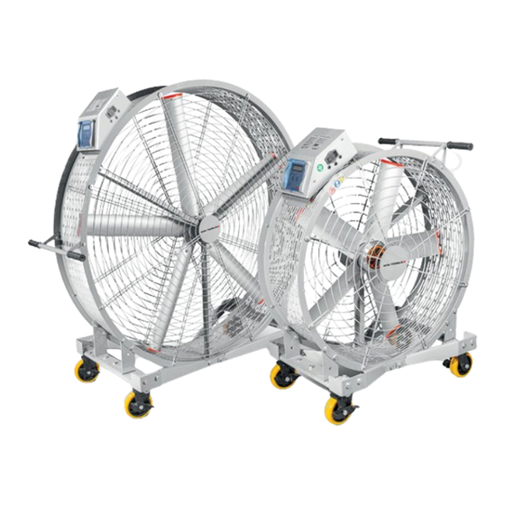
Industriële ventilator
Ventilateur industriel
Industrial fan
MV900IL
Advertisement
Table of Contents

Subscribe to Our Youtube Channel
Related Manuals for MW TOOLS MV900IL


Summary of Contents for MW TOOLS MV900IL
- Page 1 M1.1.MV900-1500-2000IL.NLFREN - 09122019 MV900IL MV1500IL HANDLEIDING - MODE D’EMPLOI - MANUAL MV900IL (722313605) MV1500IL (722313606) MV2000IL (722313607) Industriële ventilator Ventilateur industriel Industrial fan P.02 Gelieve te lezen en voor later gebruik bewaren P.08 Veuillez lire et conserver pour consultation ultérieure...
- Page 2 Het apparaat mag niet worden gebruikt onder ongunstige omstandigheden zoals vorst, corrosie, explosiegevaar of stofconcentraties. 2.2 Specificaties Model Spanning Vermogen Maximale snelheid Diameter Luchtstroom Netto gewicht MV900IL 230 V 500 W 700 tpm 900 mm 382 m³/min 54 kg MV1500IL 230 V...
- Page 3 M1.1.MV900-1500-2000IL.NLFREN - 09122019 3 Componentenlijst 1. Ventilator zonder cilinder 2. Handgreep 3. Vaste klemplaat 4. Wiel A. Holle kop bout M6x20 5. Beschermplaat A B. Externe zeskantbout M10x25 6. Beschermplaat B C. Externe zeskantbout M8x20 7. Vaste vierkante buis D. Externe zeskantbout M8x70 8.
-
Page 4: Elektrische Aansluiting
M1.1.MV900-1500-2000IL.NLFREN - 09122019 4 Elektrische aansluiting • Externe aansluiting van de ventilator De externe kabel wordt hieronder afgebeeld. • Interne bedrading van de bedieningsdoos De interne bedrading van de bedieningsdoos is hiernaast afgebeeld en de aansluiting is W, V, U, zonder volgorde. Als de draairichting van de ventilator omgekeerd is, moet u dan 2 van de aansluitingen wisselen. - Page 5 M1.1.MV900-1500-2000IL.NLFREN - 09122019 5 Bediening 5.1 Bedieningspaneel en weergave Het scherm op het bedieningspaneel geeft verschillende gegevens, parameters, waarschuwingen, enz. weer. • Naam en functie van elk deel Beeldscherm Weergave snelheid Geeft aan of de ventilator draait of niet Versnellingsknop Vertragingsknop Timerknop: Druk op deze knop en...
- Page 6 M1.1.MV900-1500-2000IL.NLFREN - 09122019 • Functie van de indicatielampjes Aan : De ventilator wordt ingeschakeld Branden om aan te geven dat de ventilator nog Uit : De ventilator wordt uitgeschakeld ingeschakeld is • Naam en functie van de bedieningsknoppen Nr. Knop Naam Functie Aan/Uit knop...
-
Page 7: Storingen Oplossen
M1.1.MV900-1500-2000IL.NLFREN - 09122019 • Statusweergave Zet de stroom aan. Bevestiging van de spanning: 230 Volt. Wanneer de apparaat ingeschakeld wordt, geeft de display het volgende weer: Naam Betekenis Normale status Het scherm geeft bij het opstarten OK weer, om de normale bedrijfsstatus aan te geven. -
Page 8: Consignes De Sécurité
L’appareil ne peut pas être utilisé dans de mauvaises conditions telles que des endroits présentant des risques de gel, de corrosion, d’explosion ou de concentrations de poussières. 2.2 Spécifications Modèle Tension Puissance Vitesse maximale Diamètre Débit d’air Poids net MV900IL 230 V 500 W 700 tr/min 900 mm 382 m³/min 54 kg MV1500IL 230 V 750 W... -
Page 9: Liste Des Composants
M1.1.MV900-1500-2000IL.NLFREN - 09122019 3 Liste des composants 1. Ventilateur sans le cylindre 2. Poignée 3. Plaque de serrage fixe 4. Roue A. Boulons à tête creuse M6x20 5. Plaque de protection A B. Boulon hexagonal externe M10x25 6. Plaque de protection B C. -
Page 10: Branchement Électrique
M1.1.MV900-1500-2000IL.NLFREN - 09122019 4 Branchement électrique • Branchement externe du ventilateur Le câble externe est illustré ci-dessous. • Câblage interne du boîtier Le câblage interne du boîtier est illustré ci-contre, et la connexion est W, V, U sans ordre. Si le sens de rotation du ventilateur est inversé, échangez 2 des connexions. - Page 11 M1.1.MV900-1500-2000IL.NLFREN - 09122019 5 Utilisation 5.1 Panneau de commande et affichage L’écran sur le panneau de commande affiche plusieurs données, paramètres, avertissements, etc. • Nom et fonction de chaque partie Écran d’affichage Affichage de la vitesse Indique si le ventilateur tourne ou non Bouton d’accélération Bouton de décélération...
- Page 12 M1.1.MV900-1500-2000IL.NLFREN - 09122019 • Fonction des voyants Allumé : Le ventilateur s’allume S’allument pour indiquer que le Éteint : Le ventilateur s’arrête ventilateur est toujours en marche • Nom et fonction des boutons de commande N° Bouton de Fonction commande Bouton Marche/Arrêt Pour allumer et éteindre le ventilateur Réglage de la vitesse...
-
Page 13: Résolution Des Pannes
M1.1.MV900-1500-2000IL.NLFREN - 09122019 • Affichage du statut Mettez l’appareil sous tension. Confirmation de la tension : 230 Volts. Lorsque l’appareil est mis sous tension, l’écran affiche les données suivantes : N° Signification Statut normal L’écran affiche OK au démarrage pour indiquer le statut normal de fonctionnement. -
Page 14: Safety Instructions
The unit must not be operated in bad conditions, such as freezing, corrosion, explosion and dust concentration. 2.2 Specifications Model Voltage Power Maximum speed Diameter Air flow Net weight MV900IL 230 V 500 W 700 rpm 900 mm 382 m³/min 54 kg MV1500IL 230 V... - Page 15 M1.1.MV900-1500-2000IL.NLFREN - 09122019 3 Name of each part of the fan 1. Fan outside the cylinder 2. Handle 3. Fixed cushion plate 4. Wheel A. Socket head bolt M6x20 5. Protective plate A B. Outside hexagonal bolt M10x25 6. Protective plate B C.
-
Page 16: Electrical Connection
M1.1.MV900-1500-2000IL.NLFREN - 09122019 4 Electrical connection • Fan external connection The external installation wiring is shown in picture below. • Inner wiring of the box The inner wiring of the ceiling fan is shown in the diagram, and the connection is W, V, U, in no order. -
Page 17: Operation
M1.1.MV900-1500-2000IL.NLFREN - 09122019 5 Operation 5.1 Control panel and display The screen on the control panel displays various kinds of data, parameters, warnings, etc. • Name and functions of each section Data display Speed display Shows the fan is running or not Acceleration key Deceleration key Timing button: Press this... - Page 18 M1.1.MV900-1500-2000IL.NLFREN - 09122019 • Functions of the indicators Light: the fan starts Light up in order to keep the fan Out: the fan stops in gear • Names and functions of the control panel keys Nr. Control key Name Function Run/Stop key To start and stop the fan Acceleration key...
-
Page 19: Troubleshooting
M1.1.MV900-1500-2000IL.NLFREN - 09122019 • Status display Switch on power. Voltage confirmation: 230 Volts. When the power is switched on, the display appears as follows: Name Content Normal time Displays OK at startup for normal running state. Displays STOP when closing Failure time E-IPM Display E-IPM to indicate failure of the fan. - Page 20 Hereby declares that the following product : Product Industriële ventilator Produit Ventilateur industriel Product Industrial fan Order nr. : MV900IL (722313605) MV1500IL (722313606) MV2000IL (722313607) Geldende EG-richtlijnen 2014/35/EU - 2014/30/EU Normes CE en vigueur EN 60335-1:2012+A11:2014+AC:2014 Relevant EU directives EN 60335-2-80:2003+A1:2004+A2:2009...
Need help?
Do you have a question about the MV900IL and is the answer not in the manual?
Questions and answers