Advertisement
Quick Links
Thank you for purchasing a Sealey product. Manufactured to a high standard, this product will, if used according to these
instructions, and properly maintained, give you years of trouble free performance.
IMPORTANT: PLEASE READ THESE INSTRUCTIONS CAREFULLY. NOTE THE SAFE OPERATIONAL REQUIREMENTS, WARNINGS & CAUTIONS. USE
THE PRODUCT CORRECTLY AND WITH CARE FOR THE PURPOSE FOR WHICH IT IS INTENDED. FAILURE TO DO SO MAY CAUSE DAMAGE AND/OR
PERSONAL INJURY AND WILL INVALIDATE THE WARRANTY. KEEP THESE INSTRUCTIONS SAFE FOR FUTURE USE.
Refer to
Wear eye
instruction
protection
manual
1. SAFETY
WARNING! Wear approved eye protection. Wear appropriate Personal Protective Equipment. A full range of Personal Protective
ˆ
Equipment is available from your Sealey stockist.
WARNING! Ensure that Health & Safety, Local Authority Regulations and general workshop practice Regulations are adhered to
ˆ
when using tools.
DO NOT use tools if damaged.
8
Maintain tools to ensure that they are in an adequate condition for safe use and optimum performance.
9
Ensure that a vehicle that has been raised by a jack is adequately supported. Use axle stands.
9
Wear suitable clothing to avoid snagging. DO NOT wear jewellery. Tie back long hair.
9
Account for all tools, parts and components being used. DO NOT leave these in or near the engine. Return tools to suitable
9
storage after use.
▲
IMPORTANT! These Instructions are provided as a guide only. Always refer to the vehicle manufactures' service instructions or a
proprietary manual to establish the correct procedure and data.
WARNING! The warnings, cautions and instructions in this manual cannot cover all possible conditions and situations. The
ˆ
Operator / user must apply caution and common sense (good practical sense).
When timing an engine, always prevent the engine from being turned over. Use a notice and/or inhibit the engine.
9
WARNING! Incorrect or out of phase camshaft timing can result in contact between the valve head and the piston crown. This will
ˆ
cause damage to the engine.
2. INTRODUCTION
Covers the new generation 3 and 4-cylinder common rail diesel engines. Includes the tools required for setting the camshaft drive
gears within the cylinder head.
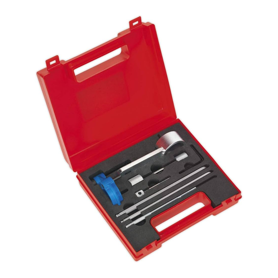
3. CONTENTS
Item
Part no.
1
VS5170.01
2
VS5170.02
3
VS5170.03
4
VS5170.04
5
VS5170.05
6
VS5170.06
7
VS5170.07
8
VS5170.08
Associated Tools
VSE5852
VS783
© Jack Sealey Limited
DIESEL ENGINE TIMING TOOL KIT - FOR VAG 1.4D,
1.6D, 2.0D - BELT DRIVE
MODEL NO:
Description
OE Tool
Crankshaft locking tool
T10490
Camshaft/H.P. pump
T10492
locking pin
Camshaft/H.P. pump
T10051
sprocket holding tool
Camshaft/H.P.pump
VAG3359
locking pin
Auxillary belt tensioner
T10060A
locking pin
Tensioner adjuster
T10409
Tensioner adjuster
T10264
Tensioner locking tool
T10265
Service position front
end support guide -
VAG
Universal pulley & fan
clutch holder set
Original Language Version
VS5170
VS5170
Issue 8 (3)
20/02/24
Advertisement

Subscribe to Our Youtube Channel
Related Manuals for Sealey VS5170


Summary of Contents for Sealey VS5170
- Page 1 VS5170 MODEL NO: Thank you for purchasing a Sealey product. Manufactured to a high standard, this product will, if used according to these instructions, and properly maintained, give you years of trouble free performance. IMPORTANT: PLEASE READ THESE INSTRUCTIONS CAREFULLY. NOTE THE SAFE OPERATIONAL REQUIREMENTS, WARNINGS & CAUTIONS. USE THE PRODUCT CORRECTLY AND WITH CARE FOR THE PURPOSE FOR WHICH IT IS INTENDED.
- Page 2 Fig.2 5.1.7. Rotate the auxiliary belt tensioner in an anti-clockwise direction to release tension from the belt, retain the tensioner in position using VS5170.05 tensioner locking pin. 5.1.8. Remove the auxiliary belt from the engine. Note: If the auxiliary belt is to be refitted, mark the direction of rotation on the belt before removing it from the engine. Refitting a used auxiliary belt in the opposite direction of rotation may cause premature failure of the belt.
- Page 3 Check that the location fork of the camshaft hub is positioned at approximately 7 o’clock relative to the camshaft central bolt (just before it reaches the location hole in the cylinder head). If it is approximately 180° out of position, remove VS5170.01, rotate the crankshaft 1 full turn and check the positions again.
- Page 4 Continue to rotate the crankshaft in the normal direction of engine rotation until the locking pin of VS5170.01 crankshaft locking tool is aligned with the moulded location pocket in the crankshaft seal housing. 5.1.16. Ensure that the body of VS5170.01 is fully located on the crankshaft sprocket, then slide the locking pin into the pocket of the crankshaft seal housing. Fig.9 5.1.17.
- Page 5 5.2.11. Ensure that the body of VS5170.01 is fully located on the crankshaft sprocket, then slide the locking pin into the pocket of the crankshaft seal housing. IMPORTANT: Engine setting/locking tools MUST NOT be used to counter-hold the camshaft or high pressure pump when releasing or tightening the sprocket nuts/bolts.
- Page 6 Using a suitable tensioner adjuster, rotate the tensioner in an anti-clockwise direction to release tension from the belt. If a type 2 tensioner is fitted, install VS5170.08 Tensioner Locking Pin through the aperture in the front of the tensioner hub.
- Page 7 Remove VS5170.08 Tensioner Locking Pin. 5.2.34. Using VS5170.07 or VS5170.06 Tensioner Adjuster, rotate the eccentric hub of the tensioner pulley in a clockwise direction until the tension indicator arrow is aligned with the slot in the tensioner body. Original Language Version...
- Page 8 Rotate the crankshaft 2 full turns in the normal direction of engine rotation until the guide peg of the crankshaft sprocket is positioned at approximately 7 o’clock relative to the central bolt. Original Language Version VS5170 Issue 8 (3) 20/02/24 © Jack Sealey Limited...
- Page 9 5.2.43. Ensure that the body of VS5170.01 is fully located on the crankshaft sprocket, then slide the locking pin into the location pocket of the crankshaft seal housing, see fig.8.
- Page 10 5.2.55. Ensure that the body of VS5170.01 is fully located on the crankshaft sprocket, then slide the locking pin into the location pocket of the crankshaft seal housing.
- Page 11 5.2.63. Ensure that the body of VS5170.01 is fully located on the crankshaft sprocket, then slide the locking pin into the pocket of the crankshaft seal housing, see fig.34A.
- Page 12 Fig.46 5.2.67. Using VS5170.03 Sprocket Holding Tool as a counter-hold, tighten the central nut of the high pressure fuel pump sprocket to its final torque setting of 95Nm. IMPORTANT: Engine setting/locking tools MUST NOT be used to counter-hold the camshaft or high pressure pump when releasing or tightening the sprocket nuts/bolts.
- Page 13 Insert VS5170.02 camshaft locking pin through the aperture in the camshaft cover until the pin is fully located in the camshaft. When VS5170.02 is correctly fitted there will be a gap of 1mm between the head of VS5170.02 camshaft locking pin and the plastic camshaft cover.
-
Page 14: Environment Protection
Check the engine timing as described in section 5.1 “Engine Timing – Check”. 5.3.12. Insert VS5170.02 camshaft locking pin through the aperture in the camshaft cover until the pin is fully located in the camshaft to check the positioning of the inlet camshaft.
Need help?
Do you have a question about the VS5170 and is the answer not in the manual?
Questions and answers