
Related Manuals for GE UNC15NJ II


Summary of Contents for GE UNC15NJ II
- Page 1 GE Appliances Technical Service Guide November 2016 Nugget Ice Maker UNC15NJ_II GE Appliances 31-9260 General Electric Company Louisville, Kentucky 40225...
-
Page 2: Safety Information
GE Appliances Technical Service Guide Copyright © 2016 All rights reserved. This service guide may not be reproduced in whole or in part in any form without written permission from GE Appliances. – 2 –... -
Page 3: Table Of Contents
Table of Contents Safety Information ..................................2 Table of Contents ..................................... 3 Safety Requirements ..................................6 Nomenclature ....................................7 Introduction ....................................... 8 Important Safety Information ..............................10 Technical Data ....................................12 Ice Maker Location and Preparation ............................13 Prior to Installation ..................................15 Installation Requirements ................................ - Page 4 Operating Instructions ................................. 34 Maintenance and Cleaning ................................ 35 Component Locator Views ................................38 Cabinet and Structure ................................... 48 Kick Plate ....................................48 Access Cover ................................... 48 ................................48 Installing Stainless Steel Door Panel ..........................50 Hinge System ..................................51 Leveling Legs ..................................
- Page 5 Auger Drive Motor/Gear Reducer System ......................... 76 Gear and Evaporator Shelf Assembly ......................... 78 Sealed System ....................................79 Compressor ..................................... 80 Evaporator ....................................83 Condenser ....................................86 Troubleshooting ....................................88 Schematics / Wiring Diagrams ..............................90 Warranty ......................................92 Index ........................................93 –...
-
Page 6: Safety Requirements
Safety Requirements GE Factory Service Employees are required to use safety glasses with side shields, safety gloves and steel toe shoes for all repairs. Electrically Rated Glove and Steel Toed Work Boot Dyneema® Cut Resistant Dyneema® Cut Resistant Glove Glove Keeper... -
Page 7: Nomenclature
Nomenclature U N C 1 5 N J B I I Brand U - GE branded (Profile Ice Machine) Color Type II - Panel Ready/Panel Required N - Nugget Ice SS - Stainless Steel Exterior/SS Handle Appearance Engineering Digit C- Panel Ready... -
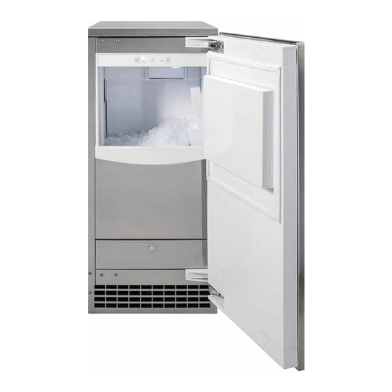
Page 8: Introduction
Introduction Introducing GE Appliance Nugget Ice Maker The UNC15NJII Nugget Ice Maker provides the consumer with a soft chewable ice nugget. The nugget ice is formed by forcing soft ice through tapered holes where they are broken into small pellets and stored in an ice make the beverage more enjoyable. - Page 9 Introduction (continued) The UNC15NJBII is considered an unbranded ice maker, meaning there is no GE or Monogram logo on the PIP70SS door accessory ZIP80SS door accessory – 9 –...
-
Page 10: Important Safety Information
Important Safety Information ICE MAKER SAFETY INFORMATION This is the safety alert symbol. This symbol alerts to potential hazards that can kill or hurt you and others. All safety messages will follow the safety alert symbol and the word “DANGER”, “WARNING”, or “CAUTION DANGER Indicates a hazardous situation which, if not avoided, will result in death or serious injury. - Page 11 Important Safety Information (continued) Explosion Hazard. WARNING INSTALLATION OUTDOOR USE NOTICE: KEEP FROM FREEZING: Severe damage will occur to WATER SUPPLY: Avoid a long run of hose or tubing the unit if left in or operated in temperatures beyond exposed to the sun. Plastic water supply tubing the limits listed in this manual.
-
Page 12: Technical Data
Technical Data • Rated Voltage: 104 - 126 VAC • Water Sensor: • Circuit Breaker: 15 - amp • Millivolts • Refrigerant Charge: 4.5 oz. R-134a • Conductivity, 10 microsiemens/cm and greater • Control Board: Operation input 12 VAC • User Interface: ~2 - 6 VDC Operation Limits •... -
Page 13: Ice Maker Location And Preparation
Ice Maker Location and Preparation Ice Maker Location and Preparation Water Quality This ice maker is designed to be used indoors in a All water, including potable water supplied by controlled environment, or outdoors within certain municipalities, contains some impurities or minerals. limits. - Page 14 Ice Maker Location and Preparation (continued) Filters and Treatment well as particles. We recommend using a GE Water Filter on your water inlet line such as GE Model Number GXRLQ. Please go to www.geappliances. com to review the installation instructions and Canada visit www.GEAppliances.com.
-
Page 15: Prior To Installation
Prior to Installation Installation Overview Installation Over A Crawl Space or Basement: Either a gravity drain or a pump may be used. For The ice maker must: pump, see Installation Notes, Accessories. If there is not enough room behind the machine for a drain •... -
Page 16: Installation Requirements
Installation Requirements Electrical Power For Gravity Drain Installation The unit must be on its own 115 volt, 60 Hz, 15 amp • Drain tube must not trap water circuit. It is equipped with a power cord and can be • Route and slope to drain, following all plugged into a nearby outlet. -
Page 17: Accessories
Accessories Finished stainless steel door panels are available from GE Appliances for attachment to the ice maker. The panel kits are: • ZIP80SS: Stainless steel door with Euro Style Handles • PIP70SS Handles To order, go to www.GEApplianceParts.com or call 877-959-8688. -
Page 18: Installation Instructions
Installation Instructions 9. Remove the screw holding the hole cover to the Door Swing The door can be attached to open with hinges on 10. Remove the screws holding the door panel to the left or right. Retain all screws for reuse. door, and separate the panel from the door. -
Page 19: Installing Door Panel
Door Panel marking. Use a drill stop to prevent drilling through the panel. Finished stainless steel door panels with handles are available from GE Appliances for attachment to the 3 9/ 6 ice maker. See Installation Notes, Accessories. 6-25/32" 6-25/32”... - Page 20 Installation Instructions (continued) 4. Fasten the panel to the door using the 6 Installing Door Panel (continued) sheet metal screws. In the hinge area, use the Attaching the Door Panel (Accessories) outermost screw holes. The panel will be held on by 6 sheet metal screws 5.
-
Page 21: Installing Extended Kick Plate (Accessory)
Installation Instructions (continued) Installing Door Panel (continued) Installing Extended Kick Plate (Accessory) 9. Slide the hinge covers from the hardware packet The extended kick plate is installed behind the over each hinge. existing kick plate if there is a large gap between the 10. -
Page 22: Installing Anti-Tip Bracket (Accessory)
Installation Instructions (continued) Installing Anti-Tip Bracket (Accessory) Plumbing The anti-tip bracket is used to attach the ice maker The recommended water supply tubing is 1/4 in. OD to the wall for stability and as a safety precaution. may also be used. Install an easily accessible shut- 1. -
Page 23: Gravity Drain
7. Reinstall the upper back panel. Gravity Drain 8. Reinstall the service access panel. Level the unit. Drain Installation There are leg caps in the hardware packet that can snap onto the leveling legs if they are going NOTICE: Restrictions in the drain system to the to show when the unit is level. -
Page 24: Drain Pump Kit Upk3 (Accessories)
Drain Pump Kit UPK3 (Accessories) KIT CONTENTS: 6. Stainless steel shield (for use in cube models only) 1. Pump and motor with check valve 2. Switch mounting bracket assembled to switch assembly 8. Hose clamp 3. Wire harness 9. Two screws with lock washers 4. - Page 25 Drain Pump Kit UPK3 (continued) 4. REMOVE EXISTING DRAIN HOSE C. Remove the screws from the back panel. Remove the existing drain hose. The drain hose is the upper left hand corner of the side service panel to install the new drain hose. UNC15 Nugget Model Screw...
- Page 26 Drain Pump Kit UPK3 (continued) C. Place the pump over the bolts located on the G. Mount the switch assembly bracket to the base base of the ice maker and secure with the 2 using 2 provided sheet metal screws and lock nuts and washers provided in the kit.
- Page 27 Drain Pump Kit UPK3 (continued) 6. FLUSH OUT THE DRAIN HOSE A. Restore power to the unit. B. With the unit still OFF, pour several quarts of water into the bin. The drain pump should turn on and pump the water out of the bin, cycling Pump cycling is normal since the pump-out rate of the drain pump is greater than the rate of drain through the bin.
-
Page 28: Sequence Of Operation
Sequence Of Operation Initial Start-Up Sequence of Events • Power and water on • reservoir and evaporator • Water sensor detects water • Ice bin sensor – Need for ice • Control board starts: • Compressor • • Auger drive motor start: In 10 minutes ice will •... -
Page 29: Components Systems Operations
Components Systems Operations • Refrigeration System: Including air cooled condenser, compressor, capillary tube and evaporator • Control System: Including ice level sensor, water sensor, auger motor sensor, user interface, control pad and transformer • Auger Drive System: Including auger motor, gear reducer and auger •... -
Page 30: Control System
Control System The control system operates the ice maker. The control board operates on 12 VAC, supplied by the transformer. It uses an ultrasonic ice sensor to measure the ice level. The ultrasonic system transmits sound waves into the ice storage bin and measures the return time. When the return time is longer than the pre-set time for a full bin, the control board switches the ice maker to an ice making mode. -
Page 31: Water System
Water System The auger is driven at approximately 11 RPM by the gear reducer. The gear reducer is a sealed component and does not require lubrication, as it contains a charge of grease. The auger motor drives a set of gears that all together reduce the motor speed to the 11 RPM output speed, and correspondingly increases the torque. -
Page 32: Storage
Storage The ice storage system is made up of a plastic lined ice storage bin, covered by an insulated top panel and an insulated swing open door with gasket. The ice storage bin is foamed in place, so the side panels are not removable. -
Page 33: Control Features
Control Features 1. POWER ON/OFF 2. ICE MAKING: Illuminates white when ice maker is turned on. 3. CHECK WATER: Illuminates red when water is not detected in the water reservoir. 4. TIME TO CLEAN: Illuminates yellow when it's time to clean the ice maker. The LED will switch ON after 6 months of use. -
Page 34: Operating Instructions
Operating Instructions Initial Start Up 1. Turn on the water supply. 2. Switch on the electrical power. 3. Push and release the ON/OFF switch to start the machine. The ICE MAKING light next to the ON/OFF switch will glow white. It will take about 10 minutes for the ice machine to begin dropping nugget ice into the storage bin. -
Page 35: Maintenance And Cleaning
Maintenance and Cleaning Cleaning the Condenser 3. Open the door and locate the screws at the upper back wall of the bin. Remove the 2 screws. clogged with dirt and lint. To clean: 1. Remove the kick plate and front service panel. 2. - Page 36 Maintenance and Cleaning (continued) Removing Scale from the Ice Making System NOTE: Take care not to spill any scale remover on (Continued.) nearby surfaces. Immediately wipe any spill with baking soda and water. 6. Locate the ON/OFF lever. Move the 9.
- Page 37 Maintenance and Cleaning (continued) Winterizing CAUTION 1. Clean the ice making system per the instructions under Removing Scale from the Ice Making System. 2. Open the door. Push the ON/OFF button to turn 4. Drain the water reservoir by removing the drain plug under the reservoir.
-
Page 38: Component Locator Views
Component Locator Views Top Hinge Rail POWER CLEAN ON/OFF CHECK TIME TO RESET MAKING WATER CLEAN User Interface Front Access Panel, (Phillips screw behind plug) Mini Manual behind service panel Ice Scoop Kick Plate – 38 –... - Page 39 Component Locator Views (continued) Door Hinge Hinge Cover, Hinge side Outer Door Clad Accessory Hinge Cover Hole Plug Door Hinge Hinge Cover, Hinge side Door Gasket Door Assembly Hole Plug Hinge Cover – 39 –...
- Page 40 Component Locator Views (continued) Harness, Bin LED/Reed Control Switch Cover Control Board Ice Level Sensor Control Housing Transformer User Interface LED Lamp Light Cover – 40 –...
- Page 41 Component Locator Views (continued) 1/4" Copper Tubing Harness, Water Sensor Sleeve Water Sensor 1/4" Compression Nut and Ferrule Water Reservoir Cleaning Process) Outlet to Evaporator Support, Water Reservoir – 41 –...
- Page 42 Component Locator Views (continued) Reservoir Tube Bracket Support, Left Side Shelf, Gear and Evaporator assy. Thumb Screw Bracket Support, Right Side Drain Plug Insulation, Ice Drain Tube Cover Cover, Ice Compartment – 42 –...
- Page 43 Component Locator Views (continued) Screw, 5/16-18 Ice Sweep Evaporator and Auger Drive Assembly Ice Chute (one assembly) Vibration Grommet Grommet Mounting Plate Flanged Bushing Washer Cap Screw – 43 –...
- Page 44 Component Locator Views (continued) 1/4" Allen Screw Breaker Head with/Bearing O-ring Rotating Seal 5/32" Allen Stationary Seal Screw Adapter Auger Water Shed Gear Reducer Drive Assembly – 44 –...
- Page 45 Component Locator Views (continued) Gasket Shroud, Condenser Compressor Clip Grommet Condenser Fan Blade, Fan, Motor, and Fan Bracket (Items are ordered separately) Leveling – 45 –...
- Page 46 Component Locator Views (continued) Heat Evaporator Exchanger Process Tube Compressor Discharge Tube Drier Hot Gas Tube Condenser – 46 –...
- Page 47 Component Locator Views (continued) Hose Clamp Gravity Drain hoses and clamps Drain Hose Hose Clamp Elbow Optional drain pump assembly UPK3 Discharge Hose Check Valve Hose Clamp Hose Clamp Drain Tube Pump and Motor Hose Clamp Bracket, Pressure Pressure Switch Switch Hose, Pressure...
-
Page 48: Cabinet And Structure
Cabinet and Structure Kick Plate machine area components and to provide access hinges allows the door to open from either the left or for maintenance. Never block or restrict the kick the right side. Change the swing BEFORE attaching plate area. the door panel. - Page 49 IMPORTANT: In some situations, the door can open Finished stainless steel door panels with handles are too far and damage adjacent cabinets. To prevent available from GE Appliances for attachment to the this, insert a Stop Pin (included in the hardware ice machine. See Installation Notes, Accessories.
-
Page 50: Installing Stainless Steel Door Panel
5. Place the covers over the hinge opening areas Installing Stainless Steel Door Panel and secure each cover to the door using a sheet metal screw and washer. NOTE: If the door swing is going to be changed, please complete prior to installing the door panel. 6. -
Page 51: Hinge System
Hinge System To replace the ice maker door hinges, the door outer clad will need to be removed. If the ice maker door needs reversing the door will need to be removed from the cabinet, see the section. Hinge Removal 1. -
Page 52: Leveling Legs
Leveling Legs Top Cover The top cover is secured to the ice maker by 2 the ice maker's leveling. The ice maker must be level Phillips screws located in the back of the ice maker. to ensure proper functioning. The top cover contains EPS (Styrofoam), and a foam taped gasket. -
Page 53: Side Service Panel
Side Service Panel Back Panel The side service panel allows for service to the The back panel allows for access to the rear machine compartment components such as the components of the ice maker as well as condenser fan motor, hot gas solenoid, water valve, providing structural strength. -
Page 54: Ice Maker Cabinet
13. Remove 3 Phillips screws located on the bottom, Ice Maker Cabinet behind the side access panel. The ice maker cabinet is the insulated component that houses all of the devices that make up the complete ice maker. The ice maker cabinet comes complete with foam insulation, stainless cabinet wrap, ice bin, bottom drain connection and an ice scoop holder. - Page 55 place it on a protective surface. Ice Maker Cabinet Installation 1. Reverse the ice maker removal procedures. 2. Ensure that all of the wiring and ground connections are properly connected. 3. Reconnect the water and drain connections. 4. Carefully reconnect power. 5.
- Page 56 6. Disconnect the condenser fan connector. Condenser Fan 7. Remove 4 Philips head screws securing the fan The condenser fan is located in the front right of brackets to the shroud. the machine compartment, and can be accessed through the right side access panel. The 120 VAC fan motor has a resistance of 196 ohms.
-
Page 57: Control Housing
Control Housing Removal Control Housing 1. Carefully remove the hinge and the door from The control housing is located in the front top the ice maker. section of the ice maker, and houses the following components: control board, LED and door reed 2. - Page 58 4. Disconnect the ground wire, (cabinet to J1). 5. Disconnect the black and white wires from the transformer. NOTE: The J1 connector, J5 connector, and user interface ribbon can remain plugged in on the control board when removing the control housing. 6.
-
Page 59: Transformer
Transformer Removal Transformer 1. Remove power to the ice maker. The transformer receives 120 VAC line voltage through the black and white wires and steps that 2. Access the control housing (see the Control voltage down to 12 VAC. Secondary voltage from the Housing section of this guide). - Page 60 Diagnosing the Bin LED and Reed Switch reed switch away from the control housing. The 1. Activate the bin LED by using a magnet and reed switch is mounted to the control housing placing the magnet approximately two inches with double sided tape. to the right of the clean button on the control panel.
-
Page 61: Control Board
Control Board J9, 24 VDC Bin Ice Level Sensor Connector J4, 120 Auger Gear VAC Output Drive Motor LED Connector J7, Water Sensor connector (millivolts) Board Power J1 12 VAC from Compressor/Condenser J5, 12 VDC Bin LED Transformer and reed switch User Interface connector Ribbon... - Page 62 Flash Information Diagnosing The Control Board • Is the board power LED on? • All blink once and repeat every 2 seconds: Auger motor overload Yes: See the Troubleshooting section for device(s) not operating in this guide. • All blink twice and repeat every 2 seconds: Auger motor low current No: Check the transformer for 12 VAC, see Diagnosing the Transformer in the...
- Page 63 Control Board Removal 1. Access the control housing (see the Control Housing section of this guide). 2. Unplug all of the control board connectors. 3. Remove 4 Phillips screws from the control board and remove the control board from the control housing. The diagram below shows the auxiliary drain pump and the L1 circuit to the control board and the transformer.
-
Page 64: Ice Level Sensor
Diagnosing The Bin Ice Level Sensor Ice Level Sensor 1. Access the control housing (see the Control The bin ice level sensor is located in the control Housing section of this guide). housing, secured to the housing with 5 Phillips screws. -
Page 65: User Interface
7. Safely reconnect power and check UI operation. User Interface • If UI starts functioning, reinstall the ice The User Interface control (UI) has two buttons, maker and check operation. POWER ON/OFF and CLEAN RESET. The UI also has 3 operation LED's: ICE MAKING (white LED), CHECK •... -
Page 66: Ice Bin And Ice Making Systems
Ice Bin and Ice Making Systems Ice Bin Components The ice bin collects nugget ice that is produced by the ice maker. The ice bin is an insulated non- refrigerated section. The ice collected in the ice bin melts slowly, ensuring that there is always fresh ice available. -
Page 67: Ice Making System
Ice Making System Water Reservoir The ice making system consist of the water reservoir, The water connected reservoir tubing, ice chute, ice sweep, evaporator, auger drive system, auger mounting sensor and plate, and gear and evaporator shelf assembly. part of the water reservoir and cannot be replaced separately. - Page 68 Water Reservoir Removal 10. Turn water reservoir on its side and remove two Phillips screws holding it to the bracket. 1. Remove power to the ice maker. 2. Remove the drain plug and empty the water reservoir and evaporator. drain connection. from its installation.
-
Page 69: Water Sensor
Diagnosing Faulty Water Sensor Water Sensor Check the water level sensor. If the CHECK WATER The water sensor is made up of two stainless steel LED is blinking: rods that measure the waters conductivity. The water sensor is located in the water reservoir on 1. - Page 70 11. Check the plug connection at the J7 connector NOTE: The water sensor is made up of two stainless on the control board. steel rods with two spade connectors. Unless the water sensor is damaged, component failure is not 12. Unplug the water sensor wiring at the water likely.
-
Page 71: Auger Drive System
Ice Sweep Diagnosis Auger Drive System • Check the ice sweep for a broken blade or if the The auger drive system contains the auger, gear plastic and drive motor, breaker assembly, ice sweep, stainless fastener bolt. auger mounting plate, water shield, adapter plate, stationary water seal, rotating water seal and ice chute. -
Page 72: Breaker Assembly
Diagnosing Breaker Assembly Breaker Assembly • Visually inspect the inner part of the breaker The breaker assembly is located on and fastened to bearing for wear (black carbon residue around the evaporator by four 1/4 in. Allen screws. the bearing is normal). Inspect for an "out of roundness"... -
Page 73: Auger
Breaker Assembly Installation Auger Removal 1. Reverse removal procedures. 1. Disconnect the power and the water. 2. Insure that the lower O-ring is attached to the bottom of the breaker assembly. maker from its installation. 3. Check the ice maker for proper operation. 3. -
Page 74: Drive System Components
Drive System Components Stationary and Rotating Water Seals Drive System Removed from Ice Maker The lower portion of the auger has two seals, a stationary and a rotating seal. The water seals prevent water in the evaporator from leaking out. The stationary seal is held in place by the lower Ice Sweep collar on the evaporator and the rotating seal is... - Page 75 9. Remove 4 Phillips screws securing the gearbox 13. Remove the rotating half of the water seal from bracket to the compartment shelf assembly. the bottom of the auger. Screw hidden by gear assembly Rotating half of water seal 14. Clean the auger of any sealant at the water seal mounting position.
-
Page 76: Auger Drive Motor/Gear Reducer System
17. Remove the stationary water seal from the Auger Drive Motor/Gear Reducer System bottom of the evaporator. The auger drive system uses a 120 VAC 24 ohm motor connected to a gear reducer gearbox. The gear reducer takes high motor RPMs and reduces it to 11 RPMs. - Page 77 Possible Conditions of a Faulty Auger Drive Motor • Ice maker calling for ice and the auger gear and Gear Reducer System drive assembly is not operating. Check for 120 VAC at the auger gear drive connector blue and • Auger not operating when the ice maker is in the white wire.
-
Page 78: Gear And Evaporator Shelf Assembly
Auger Gear Drive Assembly Removal Gear and Evaporator Shelf Assembly 1. Disconnect the power and the water. The gear and shelf assembly secures the auger drive gear reducer to the ice maker. The shelf assembly 2. Remove the drain plug and drain the water from does not have functional parts, but can be replaced the reservoir and evaporator. -
Page 79: Sealed System
Sealed System Evaporator Heat Exchanger Process Discharge Condenser Tube Compressor Tube Shroud Air Baffle Drier Foam Strip Liquid Line Condenser Condenser – 79 –... -
Page 80: Compressor
Compressor Operation Information: Compressor • 120 VAC Compressor Electrical Devices • 700 BTU The compressor is located in the machine • Run amps 2.9 - 3.1 compartment, and is secured to the machine • Resistance: compartment's base pan with four grommets, •... - Page 81 9. Is compressor operating? 15. Remove the overload from the compressor check the ohm reading of the overload. The • If yes, check amps 2.9 - 3.1 reading should be 0 ohms. • If amps are below 2.9, the ice maker •...
- Page 82 compressor. 14. Recover the refrigerant using approved recovery procedures. 15. Slide the suction tube insulation away from the compressor. 16. Unbraze or cut the discharge tube and suction tubes from the compressor. If cutting the tubing, back to the new compressor. 17.
-
Page 83: Evaporator
Evaporator The evaporator is made up of a stainless steel tube, wrapped with a coil of copper and then heavily insulated. There is no refrigerant path to the water inside of the evaporator. The inside of the tube is polished and the water to form on the inside of the evaporator tube. - Page 84 The evaporator receives low pressure liquid from Checking Evaporator the capillary tube, this low pressure liquid cools 1. Access the evaporator and look for traces of oil to a desired temperature as it enters the larger residue around the evaporator and connecting diameter evaporator.
- Page 85 Evaporator Removal Evaporator Installation If the evaporator or heat exchanger needs replacing, The replacement evaporator will come with the heat the evaporator will be sent with the heat exchanger exchanger attached. attached. If one is defective, both will be replaced. 1.
-
Page 86: Condenser
Possible Conditions of Dirty Condenser Condenser • Low or no ice production The condenser is located in the front right section of the machine compartment and is secured to the • Excessive heat coming from the bottom front of air shroud with 4 Phillips screws, 2 on each side of the ice maker the condenser. - Page 87 Condenser Removal Condenser Installation 1. Disconnect power to the ice maker. 1. Install the process tube (Part #: WJ56X61) to the compressor. 2. Remove ice from the ice bin. 2. Replace the drier. Part #: WR86X93 can be used. 3. Remove the drain plug and empty the water reservoir.
-
Page 88: Troubleshooting
Troubleshooting Problem Likely Cause Probable Solution No power Plug unit into power supply Push and release ON/OFF button Restore water supply, check sensor. If R.O. water is too pure, unit cannot operate. No water, water diagnostic light is on Check Check Check auger motor for voltage, if none, replace Compressor on, fan on,... - Page 89 Troubleshooting (continued) Problem Likely Cause Probable Solution With power on and Ice Making light on, check connector, if secure jump the two middle pins Ice level sensor failure at J2 (bin stat) on the controller together. Unit should start. If it does, replace the sensor, if not, replace the controller.
-
Page 90: Schematics / Wiring Diagrams
Schematics / Wiring Diagrams Schematic Diagram DRAIN PUMP WHERE APPLICABLE DRAIN PUMP DRAIN PUMP PRESSURE SWITCH SAFETY PRESSURE SWITCH TRANSFORMER 120 VAC MOTOR 12VAC COMPRESSOR AUGER MOTOR LIGHT SWITCH 12 VDC ELECTRONIC CONTROL LIGHT SWITCHES ON THIS UNIT SHOWN IN FREEZE CYCLE WITH DRAIN PUMP IN OPERATION WATER LEVEL... - Page 91 Schematics / Wiring Diagrams (continued) WIRING DIAGRAM DRAIN PUMP WHERE APPLICABLE COMM POWER IN SAFETY PRESSURE GN/Y SWITCH LOAD COMM LINE PUMP BIN LIGHT PRESSURE TRANSFORMER MOTOR SWITCH SWITCH WATER CONDUCTIVITY LIGHT SENSOR 3 2 1 DRAIN PUMP GN/Y MOTOR AUGER ELECTRONIC ULTRASONIC...
-
Page 92: Warranty
For US Customers: This warranty is extended to the original purchaser and any succeeding owner for products purchased for home use within the USA. If the product is located in an area where service by a GE Authorized Servicer is not available, you may be responsible for a trip change or you may be required to bring the product to an Authorized GE Service location for service. -
Page 93: Index
Index Auger 12, 28, 29, 43, 44, 61, 62, 73, 74, 76, 77, 78 pressure switch 12, 26 Baffle 45 Reed Switch 40, 59, 60 bearing 31, 72, 73, 74, 77 reservoir 12, 13, 24, 28, 29, 30, 31, 33, 35, 36, 37, 54, 66, 67, Breaker 12, 44, 72, 73, 74, 77 68, 69, 70, 74, 77, 78, 81, 85, 87 Rotating Seal 44...
Need help?
Do you have a question about the UNC15NJ II and is the answer not in the manual?
Questions and answers