
Related Manuals for C&S CSENEX-I

Summary of Contents for C&S CSENEX-I
- Page 1 CSENEX-I Quick Reference Guide Current Protection & Monitoring Solution This QRG will help you step-by-step installation, operation and programming procedure. Please go through all the instructions carefully prior to implementing. C&S Electric Limited...
-
Page 2: Current Unbalance
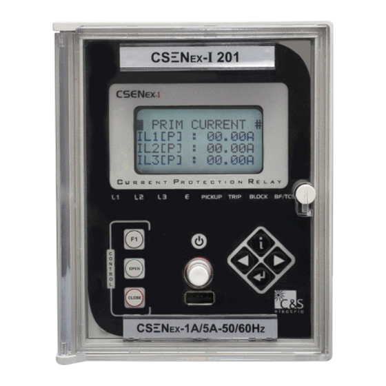
In this family of CSENEX series, the CSENEX-I is an advanced feeder protection solution which has fast, sensitive and secure protection for feeder internal & external faults. CSENEX-I offers different model based features to cover the wide range of user. Features 1A &... - Page 3 16 x 4 Alpha-numeric LCD 8 LEDs at pickup and trip on fault + 3 LEDs with special function of 3 control keys RS-485 & USB communication Front Interface of the Relay (For CSENEX-I 201 Model) L1: indicates the fault in L1 phase CSEN...
- Page 4 Front Interface of the Relay (For CSENEX-I 202 Model) L1: indicates the fault in L1 phase CSEN L2: indicates the fault in L2 phase L3: indicates the fault in L3 phase E: indicates the fault in earth U R R E N T...
- Page 5 Dimension Details CSENEX-I relay is available in a plastic case for panel or flush mounting Weight : Approx. 1.0 Kg (without cables) (All the dim. are in mm) Front View Side View 158.5 125.0 CSEN U R R E N T...
- Page 6 Connection Diagram of 201 model Earth DI 1 Power Supply DI 2 DI 3 DI 4 D0 1 D0 2 RS-485 D0 3 D0 4 Terminal Description Terminal Name Auxiliary Supply Earth A2-A3 Auxiliary Supply A4-A5 RS-485 Modbus N1(A4), P1(A5) A9-A10 Potential free Digital Output 4 A11-A12...
- Page 7 Connection Diagram of 202 model Earth DI 1 (D2 IS COMMON DI 2 Power Supply FOR DI1, DI2 & DI3) DI 3 DI 4 DI 5 DI 6 D0 1 D0 2 RS-485 D0 3 D0 4 Terminal Description Terminal Name Auxiliary Supply Earth A2-A3 Auxiliary Supply...
-
Page 8: Modbus Rtu
Rear Port (RS-485) Communication Setting Protocol MODBUS RTU Baud Rate selection 4800/9600/19200/ (programmable) 38400/57600 bps Parity Selection (programmable) Even / Odd / None Stop Bit 1 Bit Data Bit 8 Bit data Remote Address (programmable) (1 to 247) Cable required for Interface Two wire twisted shielded cable Front USB Port Communication Protocol... - Page 9 Measuring Input Rated Data Rated Current Ip :1A or 5A Rated Frequency Fn : 50 Hz/60Hz Drop out to pickup ratio >96% Power consumption At Ip = 1A 0.2 VA in current circuit At Ip = 5A 0.4 VA Thermal withstand capability Dynamic current withstand in current circuit (Half wave)
- Page 10 Model Selection Table Function ANSI NEX-I 201 NEX-I 202 CT inputs PT inputs ü ü Over current 50/51 ü ü Earth Fault 50N/51N Neutral displacement ü ü CBFP 50BF ü ü Unbalance ü ü Trip circuit 74TC Harmonic blocking ü ü...
- Page 11 Trouble Shooting Points Remedy Problem Cause of Problem POWER ON Aux Power not available/ 1) Check Aux power availability / LED not connected connection. glowing Relay not inserted properly 2) Draw out & reinstall the relay firmly & smartly. Wrong Relay not inserted properly 1) Check the BLUE LED on the measurement /...
- Page 12 NOTE content in this Document are not binding and is for general information. C&S reserves the right to change the design, content or specification contained in this catalog without prior notice. For further information, please contact: C&S Electric Ltd. (Protection & Measurement Devices) C-60, Wing-A, Phase-II, Noida-201 305, Customer Center Quick Response 1800 572 2012...
Need help?
Do you have a question about the CSENEX-I and is the answer not in the manual?
Questions and answers