Table of Contents
Advertisement
Quick Links
CSFPI-C13 Short Circuit & Earth
(CSFPI-E-B-H / CSFPI-E-C-H / CSFPI-E-D-H /
CSFPI-E-G-H model)
This QRG will help you step-by-step installation, operation and programming
procedure. Please go through all the instructions carefully prior to implementing.
Fault Passage Indicator
Quick Reference Guide
C&S Electric Limited
Advertisement
Table of Contents

Related Manuals for C&S CSFPI-C13

Summary of Contents for C&S CSFPI-C13
- Page 1 CSFPI-C13 Short Circuit & Earth Fault Passage Indicator Quick Reference Guide (CSFPI-E-B-H / CSFPI-E-C-H / CSFPI-E-D-H / CSFPI-E-G-H model) This QRG will help you step-by-step installation, operation and programming procedure. Please go through all the instructions carefully prior to implementing.
-
Page 2: Safety Precautions
Safety Precautions Under certain fault conditions, high voltages can be conducted into the fault indicator enclosure through the CT, remote indicator, or the auxiliary relay cables. All parts within the enclosure should be handled as if carrying dangerous voltages. u This product must be used only by qualified personnel practicing applicable safety precautions. - Page 3 Introduction CSFPI-Short Circuit & Earth Fault Passage Indicator is designed to detect and indicate Earth fault and Short circuit on a cable system, which can be used in RMU networks with one input / open ring arrangement. The unit will indicate a fault condition by operating alarm contacts for remote indication and by illuminating integral LEDs when current is detected above present trip current settings.
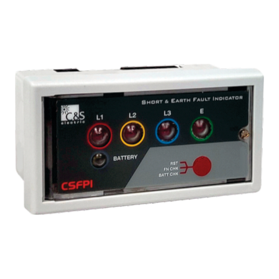
- Page 4 Front Interface / Functional Description Short Circuit Indication LED for L1, L2, L3 separately Earth Fault Indication LED HORT & ARTH AULT NDICATOR Screw BATTERY FN CHK Manual Fault Indication Reset BATT CHK CSFPI Press 3 sec & release LEDs and Relay contact Battery Status LED will operate sequentially.
-
Page 5: Functional Setting
Functional Setting... -
Page 6: Dimension Details
Dimension Details All the dimensions are in mm (Gen. Tol.: +1.0mm) Panel cut out Dimension Width 91.0 mm Height 45.0 mm FRONT VIEW OF PHASE & EARTH FAULT INDICATOR HORT & ARTH AULT NDICATOR BATTERY FN CHK CSFPI BATT CHK 97.8 mm TOP VIEW 89.5 mm... -
Page 7: Side View
Side / Back View of the Relay SIDE VIEW 51.0 mm BACK VIEW - - - - REMOTE RESET VOLTAGE RESET 97.8 mm... -
Page 8: Connection Diagram
Connection Diagram CSFPI-E-B-x RESET (230VAC) CSFPI-E-C-x RESET (230VAC) CAUTION : Remote Reset Signal requires 200msec pulse. Continuous signal can reduce battery life. - Page 9 Connection Diagram CSFPI-E-D-x REMOTE RESET (230VAC) RESET (Potential Free) CSFPI-E-G-x REMOTE RESET (230VAC) RESET (Potential Free) CAUTION : Remote Reset Signal requires 200msec pulse. Continuous signal can reduce battery life.
- Page 10 Installation of the Indication Unit The FPI indicator unit is for panel mounting. The unit is fitted on to the panel with the help of fixing clip provided. Installation of the Sensor While installing the sensors, ensure that no current is flowing through the cables.
- Page 11 Earth Sensor Locking Screw Fixing Screw Short Circuit Sensor Fixing Screw Cable Tie - - - - REMOTE RESET VOLTAGE RESET Terminal Connector...
- Page 12 Technical Data Parameters Description Short-Circuit Trip Current Adjustable: (Phase to Phase) 100/200/300/400/500/ 600/700/ 800/900/1000/ 1100/1200 A Earth-Fault Trip Current Adjustable: (Phase to Ground) 10/20/40/80/100/120/150 A Short-circuit Response Time Adjustable: 1/1.5/2/2.5/3/3.5/4/5 s Earth Fault Response Time Adjustable 1/2/3/5 s Indication Unit Suitable for panel installation Indication of a) Short-Circuit...
- Page 13 Description Parameters Type Test According to IEEE 495-2007 Operation Temperature Range : -25°C to +70°C Power Supply Lithium Battery (LiSOCl ), Type AA/ (Mandatory) 3.6V / 2.7 Ah SCADA Contact* Max 3 Nos. Latch Contacts Nominal Switching Capacity : 2A/30V DC, 0.25A/240V AC (Resistive Load) Max.
- Page 14 Short Circuit Sensor Type (CS-x-PS-x-x) Earth Fault Sensor Type (CS-x-ES-x-x) d* & Sensor cable length will be based on Sensor ordering information (Refer catalogue)
- Page 15 Trouble Shooting Points Cause of Problem Remedy Problem F u n c t i o n a l Te s t Battery voltage not 1) Try reinserting the doesn't executing available battery by opening the front cover and check. if not solved, replace the B a t t e r y s e a l n o t battery.
- Page 16 NOTE content in this Document are not binding and is for general information. C&S reserves the right to change the design, content or specification contained in this catalog without prior notice. For further information, please contact: C&S Electric Ltd. (Protection & Measurement Devices) C-60, Wing-A, Phase-II, Noida-201 305, Customer Center Quick Response 1800 572 2012...
Need help?
Do you have a question about the CSFPI-C13 and is the answer not in the manual?
Questions and answers