Advertisement
Quick Links
AR- - - - 888 Series
AR
AR
AR
AR-888PBI Request to
Exit.
888 Series
888 Series
888 Series
Technical Manual
Technical Manual
Technical Manual
Technical Manual
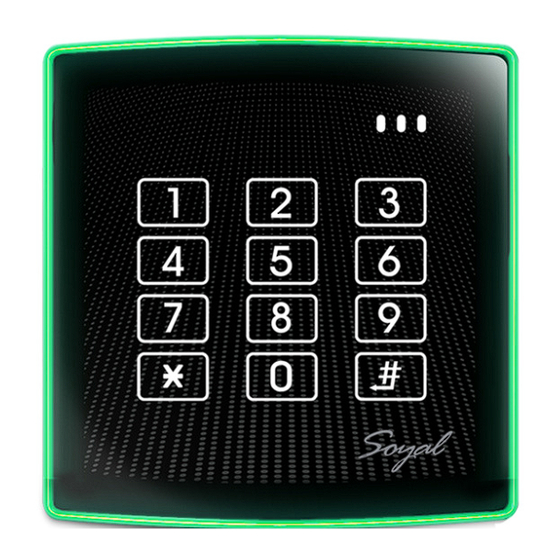
AR-888H Controller
with keypad and reader
March 2022
Version 1.00
Raytel House
Cutlers Road
South Woodham Ferrers
Essex,
CM3 5WA
Tel: (01245) 428510
Fax: (01245) 428515
AR-888U Reader
Advertisement

Related Manuals for Raytel LLC AR-888 Series

Summary of Contents for Raytel LLC AR-888 Series
- Page 1 AR- - - - 888 Series 888 Series 888 Series 888 Series Technical Manual Technical Manual Technical Manual Technical Manual AR-888PBI Request to AR-888H Controller AR-888U Reader Exit. with keypad and reader March 2022 Version 1.00 Raytel House Cutlers Road South Woodham Ferrers Essex, CM3 5WA...
-
Page 2: Table Of Contents
Modifying card data, Setting Card OR PIN, Setting Card AND PIN ..14 Setting Time Clock, Deleting Cards ............15 Command List ..................16 Additional Programming Parameters ............17 Networking and managing via Software ..........18 Lift Control ..................19 - 21 Table of Users ..................22 RSSD AR-888 Series MANUAL... - Page 3 888 Series Controllers, Readers & Exit Buttons 888 Series Controllers, Readers & Exit Buttons The AR-888 Series family of devices consist of a Controller with built in touch keypad and reader, a reader and a capacitive Exit button. Each device has on outer illuminated rim which will illuminate Red or Green depending on connections and function.
-
Page 4: Device Indicators
The Indicator LED will pulse slowly when the device is in standby mode. The Indicator LED will pulse rapidly when the controller is active. The Red and Green LED’s can be switched on and off via separate external inputs if required (CN9) RSSD AR-888 Series MANUAL... -
Page 5: Dimensions And Indications
An accepted outcome is indicated by a Green perimeter (+ one beep) A declined outcome is indicated by a Red perimeter (+ two beeps) Code entry or presentation of a Tag will result in a Green perimeter for OK and a Red perimeter for rejected. RSSD AR-888 Series MANUAL... -
Page 6: Connections
CONNECTIONS CONNECTIONS CONNECTIONS CONNECTIONS AR-888H Controller with Keypad and Reader AR-888K or AR-888U Reader / Keypad AR-888PBI Request to Exit Push Button Note: A/B Jumper selects Border colour RSSD AR-888 Series MANUAL... - Page 7 AR-888U Reader Outside Inside 12V DC PSU Clean Contacts for lock Or external AR-888H Controller lock relay (incorporates reader and keypad) Connect Door SEN to Gnd to prevent random Network Connection alarm triggering if required trigger RSSD AR-888 Series MANUAL...
- Page 8 KEYPAD OUTSIDE AR-888K Keypad Outside Inside 12V DC PSU Clean Contacts for lock or external lock relay AR-888H Controller (incorporates reader and keypad) Connect Door SEN to Gnd to prevent random Network Connection alarm triggering if required RSSD AR-888 Series MANUAL...
- Page 9 AR-888UL QR Code Reader Outside Inside 12V DC PSU Clean Contacts for lock or external AR-888H Controller lock relay (incorporates reader and keypad) Connect Door SEN to Gnd to prevent random Network Connection alarm triggering if required RSSD AR-888 Series MANUAL...
- Page 10 (Red or Green) If a traditional Exit button is required (Normally Open contacts, closing to trigger an exit command) connect the exit button between the Purple PB connection and the Black Gnd (0v) connection. RSSD AR-888 Series MANUAL...
- Page 11 The only way to access the user data without these records is by software and a USB/RS485 interface, this will only extract card data and PIN data it will not relate this data to users. RSSD AR-888 Series MANUAL...
-
Page 12: Changing Lock Time
The lock time typically is set to Minimum 001, Maximum 600 Seconds The Lock Time can be set to 000 with this setting the Lock Relay will Toggle i.e. each time a lock output is triggered the relay contacts will change state. RSSD AR-888 Series MANUAL... - Page 13 Adding a single PIN for all Users To Add a single common PIN for all Users Enter Programming Mode CURRENT MASTER CODE # COMMON PIN # Then enter When finished Exit Programming Mode CURRENT MASTER TTTTT CODE # CURRENT MASTER CODE # RSSD AR-888 Series MANUAL...
-
Page 14: Adding Tokens Or Cards
** It is important that accurate records are kept of the user addresses used and the token identities allocated to the user addresses. This will enable additional tokens to be added at a later date without accidentally overwriting existing users** RSSD AR-888 Series MANUAL... - Page 15 User address but this must be in conjunction with Card data. CURRENT MASTER CODE # Enter Programming Mode 13 UUUUU PPPP# Then Enter Where UUUUU is the 5 Digit User address and PPPP is the 4 digit PIN allocated to the user. RSSD AR-888 Series MANUAL...
- Page 16 Deleting all cards CURRENT MASTER CODE # Enter Programming Mode Then Enter Further Programming Further Programming Further Programming Further Programming Please refer to the command list and additional parameter programming information on pages 16 and 17. RSSD AR-888 Series MANUAL...
-
Page 17: Command List
128# (AR-321H, AR-721H, AR-725H, AR-757H)(changes the “Arming” 128# 128# Enable the Security Trigger in P5 to the security trigger signal. 4/8/6 Signal (with AR-721RB) 34 064# 064# (AR-331H) 34 34 000# 000# (Disable) 064# 064# 000# 000# RSSD AR-888 Series MANUAL... - Page 18 †=Default Setting C. 28*DDD# Function Function Function Function Option Option Option Option Value Value Value Value Application Application Application Application Networking/ Force Open Alarm Output Enable Stand-Alone Networking/ Force Open Alarm Output † Disable Stand-Alone †=Default Setting RSSD AR-888 Series MANUAL...
- Page 19 Number ( we would recommend setting this to 001 ) For example to set a Node ID of 22 enter 001 # 3. Exiting Programming Mode 3. Exiting Programming Mode 3. Exiting Programming Mode 3. Exiting Programming Mode RSSD AR-888 Series MANUAL...
-
Page 20: 888H Lift Control
888H LIFT CONTROL 888H LIFT CONTROL 888H LIFT CONTROL AR-401R016B Node ID=1 Lift Controller AR-321L485 Converter HOST Outside Inside 12V DC PSU Clean Contacts for lock AR-888H Controller Network Connection (incorporates reader if required and keypad) RSSD AR-888 Series MANUAL... - Page 21 27 00001 12# Will allow User 1 to access floor 12 only, on AR-401R016B set to Node 1 27 00001 22# Will allow User 1 to access floor 22 only, on AR-401R016B set to Node 2 For multiple Floor Access see the next page RSSD AR-888 Series MANUAL...
- Page 22 00022 1 10001010# = User 22, Floor Set 1, Floors 16, 12, 10 Then 00022 2 10010010# = User 22, Floor Set 2, Floors 24, 21,18 Then 00022 3 00100100# = User 22, Floor Set 3, Floors 30, 28 RSSD AR-888 Series MANUAL...
-
Page 23: Table Of Users
TABLE OF USERS TABLE OF USERS TABLE OF USERS TABLE OF USERS ____________________________________________________________________ Name of On-Site Programmer(s): ____________________________________________________________________________ Installation Company: ____________________________ Tel: DEFAULT MASTER CODE:- *123456# __________________________ Date: ______________________ Lock Time: USER MASTER CODE: ______________________ Lock Type: User Address User Address User Address User Address Users Name... - Page 24 RSSD AR-888 Series MANUAL...
- Page 25 CONTROLLER OUTSIDE CONTROLLER OUTSIDE CONTROLLER OUTSIDE CONTROLLER OUTSIDE 12V DC PSU AR-888H Controller (incorporates reader and keypad) Network Connection if required Outside Inside Clean Contacts for lock AR-888H Controller (incorporates reader and keypad) Network Connection if required RSSD AR-888 Series MANUAL...
Need help?
Do you have a question about the AR-888 Series and is the answer not in the manual?
Questions and answers