
Related Manuals for Raytel LLC AR-727E-V5

Summary of Contents for Raytel LLC AR-727E-V5
- Page 1 AR-727E-V5 Single Door Controller Installation and Programming Guide AR-727EBR1121-AJ 20th May 2021 Version 1.1 Raytel House, Cutlers Road, South Woodham Ferrers Essex, CM3 5WA Tel: (01245) 428510 Fax: (01245) 428515...
-
Page 2: Table Of Contents
CONTENTS GENERAL INFORMATION System Overview ....................Page 3 Setting Reader DIP Switches .................. Page 3 Interface Connections .................... Page 4 Reader and Lock connections ................Page 5 Display and Keypad layout ..................Page 6 Identifying Tokens and Cards ................. Page 7 PROGRAMMING Programming Tree .................... -
Page 3: System Overview
SYSTEM OVERVIEW The AR-727E-V5 Controller The AR-727E-V5 is a versatile single door proximity controller that can be used as either a stand-alone or networked device. Key Features: Built in Reader loop for token programming 16,384 User Card capacity. Alarm functions... -
Page 4: Interface Connections
INTERFACE CONNECTIONS Please Note: By default the Lock Relay output may be configured to only operate when a token is presented to the controller. To ‘Share’ the Lock Relay so that tokens presented to a connected reader or the controller both operate the Lock Relay see page xx of this guide. - Page 5 READER CONNECTIONS RSSD AR-727EBR1121-AJ Installation and Programming Manual...
-
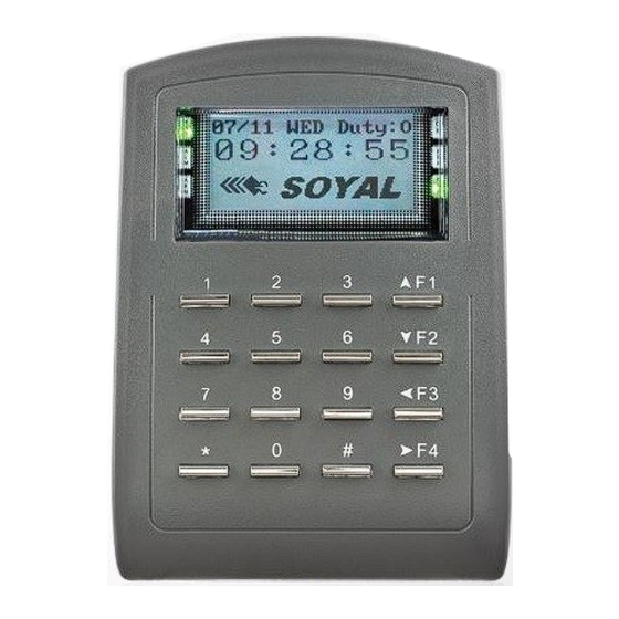
Page 6: Display And Keypad Layout
DISPLAY AND KEYPAD LAYOUT Front Panel Layout OK (Green) Power (Green) Error (Red) Alarm (Red) In Process (Green) Alarm (Green) LED’s Power (Green) Power on Alarm (Red) Abnormal condition Alarm (Green) Arming status OK (Green) Slow flash normal operation, rapid flash programming Error (Red) Indicates error IN Processing (Green) -... -
Page 7: Identifying Tokens And Cards
TOKENS / CARDS Identifying Tokens and Cards All Soyal Tokens and Cards have the Site Code and Card Code printed upon them. The Site Code and Card Code are the unique identifier for the Token or Card. The Site Code and Card Code can be located as shown below: SITE CODE CARD CODE... -
Page 8: Programming Tree
PROGRAMMING TREE 1. Add Card ID 2. Add RF Learn 3. Suspend Addr 4. Suspend 1. Add/Delete 5. Delete Addr 6. Delete 7. Recover Addr 8. Recover 9. Antipass Group 1. Password 2. User Settings 2. Access Mode 3. Extend Options 4. - Page 9 PROGRAMMING TREE Adding tokens/cards by Site Code:Card Code Adding tokens/cards by presenting them to the controllers in built reader loop. Suspending a token/card by its user address Suspending a token/card by its Site Code:Card Code Deleting a token/card by its user address Deleting a token/card by its Site Code:Card Code Recover a token/card from suspension by its user address Recover a token/card from suspension by its Site Code:Card Code...
-
Page 10: Entering And Exiting Programming Mode
PROGRAMMING Entering and Exiting Programming Mode In order to program any function of the AR-727EBRxxx Controller you must first access the programming mode by entering the factory master code. This is done as follows:- *123456# To enter programming mode press When the button is pressed after the master code has been entered, the controller will enter into programming mode and the display will show... -
Page 11: Restoring Factory Settings
PROGRAMMING Restoring Factory Settings If for any reason there is any uncertainty about which settings have been changed, it is possible to restore the original factory default settings. It is always advisable to start by performing a factory reset before commencing with any other programming. This will ensure that all settings are started from a known condition. -
Page 12: Changing Master Code
PROGRAMMING Changing Master Code It is recommended that the Master Code be changed from the factory default to keep the system secure. This is done as follows:- *123456# *MASTER CODE# Enter Programming Mode if already changed Press then press Enter the new 6 digit master code. The Display will now show Succeeded! Record the new master code on the Table of Users in the back of this manual. - Page 13 PROGRAMMING Language If, for any reason the language of the controller has been changed the display can be reset to English as follows: Enter Programming Mode Then enter The display will return to English Door Relay Time The time duration for which the lock relays are active can be adjusted between 0.1 to 600 seconds.
-
Page 14: Sharing Main Door Relay
PROGRAMMING Sharing Main Door Relay Please Note: By default the Lock Relay output may be configured to only operate when a token is presented to the controller. To ‘Share’ the Lock Relay so that tokens presented to a connected reader or the controller both operate the Lock Relay proceed as follows: Enter Programming Mode and follow the steps below until the 7th Parameter is reached (next page in Red box) all steps must be followed until ’succeeded’... - Page 15 PROGRAMMING Sharing Main Door Relay WG1 Port Generally the Main relay will be The display will be showing Share Main Relay shared. If the default is already 0:NO 1:YES 1 press # If the default is 0 press 1 on the keypad. Press dependant on default setting.
-
Page 16: Managing Tokens
MANAGING TOKENS Checking Existing Users Enter Programming Mode Press then press The display will be showing F/w Ver : xxxx Users : xxxxx Messages : xxxxx Press any key . . . F/w Ver - is the current version of Firmware installed on the controller. Users - is the current number of Users (Tokens) on the controller, please note that suspended tokens will not be shown. - Page 17 MANAGING TOKENS Using Add RF Learn to Add Single Tokens Enter Programming Mode Press then press The display will be showing User Address : F3: Prev F4: Next Range: (0-016383) xxxxxx Where xxxxxx will equal the next available User Address (On a new controller xxxxxx will equal 000001) Press For a single token the display Tag Units (pcs)
- Page 18 MANAGING TOKENS Using Add RF Learn to Add Sequential Tokens Before proceeding confirm that the tokens are sequential, confirm the quantiy and separate the lowest numbered token from the batch. Enter Programming Mode Press then press User Address : The display should be showing F3: Prev F4: Next The next free User Address (On a new Range: (0-016383)
-
Page 19: Suspending Tokens
MANAGING TOKENS Suspending Tokens by Address We recommend that tokens are suspended rather than deleted. Suspended tokens can be recovered (see pages 19-20) Suspending tokens also prevents overwriting existing tokens when using “Add by RF Learn” Before proceeding the User Address of the token(s) to be suspended will be required, refer to the table of users at the back of this manual. - Page 20 MANAGING TOKENS Suspending Tokens by Code Before proceeding the Site Codes and Card Codes of the token(s) to be suspended will be required, refer to the table of users at the back of this manual. Once Tokens are suspended when presented they will show as “Invalid User” at the controller or “Scan Data”...
-
Page 21: Recovering Tokens
MANAGING TOKENS Recovering Tokens by Address Before proceeding the User Address of the token(s) to be recovered will be required, refer to the table of users at the back of this manual. Once Tokens are suspended when presented they will show as “Invalid User” at the controller or “Scan Data”... - Page 22 MANAGING TOKENS Recovering Tokens by Code Before proceeding the Site Codes and Card Codes of the token(s) to be recovered will be required, refer to the table of users at the back of this manual. Once Tokens are suspended when presented they will show as “Invalid User” at the controller or “Scan Data”...
-
Page 23: Networking
NETWORKING Setting Node ID ( and IP Address) If controllers are networked they can be programmed and monitored remotely using dedicated software available from our website https://www.raytelsecurity.com Controllers can be networked by three different methods as follows: RS485 (controllers are connected to a RS485 network and a USB to RS485 adaptor is used at the PC) RS485 via TCP/IP (controllers are connected to a RS485 network via a TCP/IP to RS485 adaptor) - Page 24 NETWORKING Setting Node ID ( and IP Address) continued The display will show Show WG Message 0: No 1 : Enable X is the current setting, if x = 1 press if x = 0, press The display will show Enable DHCP 0 : No 1 : En 2: Exit 192.168.001.127*...
- Page 25 NETWORKING Setting Node ID ( and IP Address) continued The display will show Gateway (IPv4) 192.168.001.254 192.xxx.xxx.xxx To modify the default Gateway address over type 192.xxx.xxx.xxx with the required gateway address. At the end of this process the controller will restart and the modified settings will be active. If the controller is to be used on a network it should be selected In the LAN settings drop down of 701 Server as: 881/837/82xEv5/727Ev5/725Ev2/721Ev2...
-
Page 26: Alarms
ALARMS Setting and Configuring Door Alarms For alarms to be configured a normally closed door sensing Contact is required (if monitored mag locks are being used then monitoring contacts are built in to the mag lock) at each door where an alarm is required. The door contacts must be connected to 0V and the xxx inputs as required (See Page xx) Alarm outputs are Normally Open clean contacts that close when an alarm condition is met. - Page 27 ALARMS Door Relay Time To set the Door relay times refer to Page xx of this manual. Door Close Time The Door Close time is the amount of time from the start of the Door Open time until the Alarm is triggered. E.g.
- Page 28 ALARMS Door Close to Stop Alarm Alarms can be set to either sound for the programmed ‘Alarm Relay Time’ or alarms can be silenced by closing the door. To set the Close Door to Stop Alarm options: Enter Programming Mode. Press then press The display will now show:...
- Page 29 ALARMS Alarm Output Delay Time The Alarm Output Delay Time is the time between the Alarm condition being identified and the Alarm output switching ON. To set the Alarm Output Delay time: Enter Programming Mode. Press then press The display will now show: Alarm Output Delay Time (Secs) Range 000 - 255...
- Page 30 ALARMS Arming Password To enable Alarms to be Armed at the controller a 4 digit passcode is required. To set the Arming Passcode : Enter Programming Mode. Press then press The display will now show: Input PIN Code Range: 0000 - 9999 xxxx xxxx is the current passcode:...
- Page 31 ALARMS 701 Client-Monitoring + Arming/Disarming Doors From within the 701 Client software door alarms can be Armed, Disarmed and monitored. The screen above shows a typical event log with Alarm events, the software shows alarm events in Red text. Controllers can be armed and disarmed either via the 701 Client software or at the controller(s) By selecting G from the 701 Client header strip the ‘Reader Status Monitor and Modify ‘...
-
Page 32: Table Of Users
TABLE OF USERS ____________________________________________________________________ Name of On-Site Programmer(s): ____________________________________________________________________________ Installation Company: ____________________________ Tel: DEFAULT MASTER CODE:- *123456# __________________________ Date: ______________________ Lock Time: USER MASTER CODE: ______________________ Lock Type: User Address Users Name Card ID User Code Date We recommend this page should be filled in and regularly updated and kept in a safe and secure location by the person responsible for the upkeep of the system.
Need help?
Do you have a question about the AR-727E-V5 and is the answer not in the manual?
Questions and answers