Table of Contents
Advertisement
Quick Links
Advertisement
Table of Contents

Subscribe to Our Youtube Channel
Related Manuals for TECSYSTEM NTF999

Summary of Contents for TECSYSTEM NTF999
- Page 1 INSTRUCTION MANUAL NTF999 1MN0156 REV.0 operates with ISO9001 certified quality system TECSYSTEM S.r.l. 20094 Corsico (MI) Tel.: +39-024581861 Fax: +39-0248600783 http://www.tecsystem.it R. 1.0 29/05/2018 ENGLISH “Translations of the original instructions”...
-
Page 2: Table Of Contents
INTRODUCTION First of all we wish to thank you for choosing to use a TECSYSTEM product and recommend you read this instruction manual carefully: You will understand the use of the equipment and therefore be able to take advantage of all its functions. - Page 3 11) Pt100 EXTENSION CABLE TECHNICAL SPECIFICATIONS — ………………………………….. 12) FCD FUNCTION ………………………………….. 13) WARRANTY CONDITIONS — ………………………………….. 14) TROUBLESHOOTING ………………………………….. 15) EQUIPMENT DISPOSAL — ………………………………….. 16) USEFUL CONTACTS — ………………………………….. 17) TECSYSTEM BAR PROGRAMMING TABLE ………………………………….. 18) UL SPECIFICATION AND RATING — NTF999...
-
Page 4: Safety Requirements
SUPPLY The NTF999 control unit can be supplied either from 85 to 250 Vac. Before using it, make sure the power cable is not damaged, knotted or pinched. Do not tamper with the power cable. Never disconnect the unit by pulling the cable, avoid touching the pins. -
Page 5: Accessories
1 terminal 3 poles pitch 3.81 probes (only for option RS485) Code: 2PL0366 - Screws tightening torque 0.25Nm ATTENTION: always install the device using the terminals included in the pack. The use of terminals other than those included with the control unit might cause malfunctions. NTF999... -
Page 6: Technical Specifications
● Absorption 8VA (ventilation FAN1 and FAN2 excluded) ● ● Data memory 10 years minimum (*) The FAN1 and FAN2 outputs are powered directly by the NTF999 device, in relation to the power supply value of the device itself. NTF999... - Page 7 TECHNICAL SPECIFICATIONS NTF999 PT100 NTF999 TCK ● ● Digital linearity of sensor signal ● ● Self-diagnostic circuit Protection treatment of the electronic part Optional Optional DISPLAY AND DATA MANAGEMENT ● ● 2 x 20,5mm displays with 3 digits to display temperatures, messages and channels ●...
-
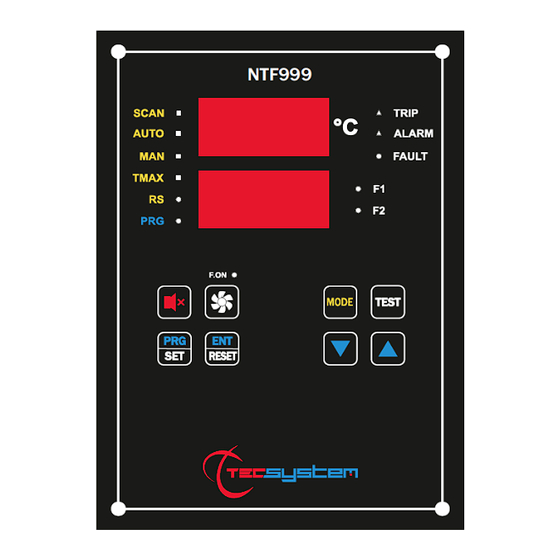
Page 8: Front Panel
RS communication (green) LED Display mode selection key T-max mode selection (red) LED Led/relay test key Man mode selection (yellow) LED UP key Auto mode selection (green) LED DOWN key Scan mode selection (yellow) LED Key enable forced ventilation NTF999... -
Page 9: Display
The second display to the monitored channel. When the device is switched on or after a reset, the display shows: the control unit model, NTF999, together with VER "00" (firmware version), communication option (RS485 or ETH) if available, option type sensor (PT100 or TCK), temperature range. -
Page 10: Mounting
Drill four holes size Ø5.5mm distance 145mm X 212mm, see drawing below. Control unit Identification label Panel hole dimensions (+0.2mm tolerance) Fixing hole distance for nylon screws. Firmly tighten the device with the 4 screws (nylon) supplied 1MN0156 REV. 0 Screws, Washers and Bolts nylon M5 Line-head screwdriver #1X100mm NTF999... -
Page 11: Electrical Connections
ELECTRICAL CONNECTIONS 1MN0156 REV. 0 NTF999 Pt100 CONNECTION EXAMPLE TCK CONNECTION EXAMPLE Power supply 85-250Vac 50/60Hz Pt100 or TCK sensors 8VA+12A max (F1-F2 6A max for line) Power Outputs ventilation (FAN2-FAN1) RS485 or ETHERNET output (85-250Vac 6A max) outputs powered. -
Page 12: Power Supply
SUPPLY The NTF999 control unit can be supplied either from 85 to 250 Vac, 50/60Hz (terminals 40-42). The ground must always be connected to terminal 41. When the unit is supplied directly by the secondary of the transformer to protect, it can be burnt out by strong overvoltages. -
Page 13: Programming
PROGRAMMING NTF999 STEP PRESS EFFECT PRESS NOTES Keep the PRG key pressed until the display shows PRG LED PRG will blink quickly Default SET/1 Select SET (for Programming Manual) tables: 1- 2-3-4-5 see at 1-2-3-4-5 table to call default programming. - Page 14 Set the desired threshold FAN2 HI From 1A to 6A END is displayed Programming end Err: incorrect Press ENT to save the set data programming of the values and exit programming indicated by the LEDs (note 6) PRG to return to step 1 NTF999...
-
Page 15: Default Programming Tables
We recommend you check the device's programming before starting the device. The default parameters set by TECSYSTEM might not match your requirements. Programming the device is the end user's responsibility, the settings of the alarm thresholds and the enabling of the functions described in this manual must be checked (by a specialised engineer) according to the application and features of the system the control unit is installed on. -
Page 16: Temperature Sensors
Pt100 sensors c) damage of the inputs of the control unit. For the Pt100 sensor connection , TECSYSTEM S.r.l. has designed its own special cable to transfer the measurement signals, CEI-compliant, with all the protection requirements provided for: CT-ES NOTE: the use of cables not complying with the above might cause reading anomalies. -
Page 17: Temperature Sensor Diagnostics
CAL message display: the indication appears when the measurement circuit is damaged. The temperature values displayed might be incorrect. Return the control unit to TECSYSTEM for repairs. VOTING FUNCTION The voting function derives from the redundancy concept that consists of duplicating the components of a system to increase their reliability. -
Page 18: Cooling Fan Control
The NTF999 control unit has two active FAN lines (FAN1 and FAN2). The outputs F1 and F2 are powered directly by the NTF999 device, in relation to the power supply value of the device itself, supply range from 85 to 250 Vac, maximum current supports 6A (10A fuse for short circuit protection). -
Page 19: Intellifan Function
The NTF999 control unit is in communication with the network only when it is in temperature reading mode, while it is inactive when it is in the following modes: display, programming and relays test. -
Page 20: Introduction To The Ethernet Module
The ETH module is always in slave mode. The NTF999 control unit is in communication with the network only when it is in temperature reading mode, while it is inactive when in the following modes: display, programming and test relays. -
Page 21: Error Codes
1 A will be stored without affecting the received message. From the point of view of the Modbus connection, the control unit is considered as a normal NTF999. At the end of the write command (Write) is carried out a check of compatibility data: ... -
Page 22: Modbus Mapping Table
Data HI Data LO Notes 1 Notes 2 (10) read/write HFN (Fan test) 0=No test 1÷200h temperature 0=No FCD increment 1÷30°/sec Voting 0=No Voting 1=YES Voting CPU Setting See Notes CPU Error See Notes See Notes Relays Status FREE FREE NTF999... - Page 23 2’compl. sign 1° ÷ 220° AS (AL) alarm set point 2’compl. Ch2 temper. 2’compl. sign 1° ÷ 220° AS (TRP) trip set point 2’compl. sign 2’compl. Ch3 temper. -23° ÷ 228 2’compl. sign 2’compl. Ch3 max temperat. 1° ÷ 220 NTF999...
- Page 24 2’compl. Ch4 temper. -23° ÷ 228 2’compl. sign 2’compl. Ch4 max temperat. 1° ÷ 220 2’compl. Ch4 temper. 2’compl. sign 1° ÷ 220 (AL) alarm set point 2’compl. Ch4 temper. 2’compl. sign 1° ÷ 220 (TRP) trip set point NTF999...
- Page 25 See Note CHx Ch4 story Ch4 status See Note CHx Various Records R: read Address W:write Data HI Data LO Notes 1 Notes 2 LO (10) read/write Prog. FAN_1 Current Prog. FAN_2 Current value = 1÷6 WRØ=1 Reserved Reserved NTF999...
- Page 26 Failsafe trip alarm TRIP ALARM (always=1) FAN STATUS BIT 7 BIT 6 BIT 5 BIT 4 BIT 3 BIT 2 BIT 1 BIT 0 Function Fan_2 HI Fan_2 LO Fan_1 HI Fan_1 LO FAN=ON Over_current Under_current Over_current Under_current NTF999...
-
Page 27: Ethernet Module Parameter Programming
ETHERNET MODULE PROGRAMMING PARAMETER X Windows Vista, 7, 8. ETH0 CONNECTIONS Using an Ethernet cable, connect the ETH0 of the NTF999 control unit to the Ethernet card of a PC. TELNET ENABLING Use the Telnet program to set the Ethernet IP parameters. -
Page 28: 12) Telnet Screen
13) Enter: OPEN 14) Press ENTER 192.168.10.120 9999 15) Enter: 16) Press ENTER 17) Enter the Password: TECS 18) Press ENTER Note: In this screen we have the MAC address and the software version of the ETH port available. NTF999... -
Page 29: 19) Ip Parameter Programming Menu
IMPORTANT WARNING For the device to work correctly, we advise you not to access or modify menus 2-3-4-7. The modification of the values in the stated menus might cause communication anomalies with the loss of the Ethernet IP communication. NTF999... - Page 30 3) Enter the new Netmask, press ENTER; if you wish to keep the set address press ENTER 4 times. At the end of the operation, the system will ask if you wish to modify the Telnet Password: Enter: to modify the Telnet Password. not to modify the Telnet Password and to skip to the following step. NTF999...
-
Page 31: Function Failsafe
FAIL SAFE FUNCTION The NTF999 has n.o selection (contact) / n.c (normally closed contact) for alarm and trip relays, programming steps 32 to 35 page 14. The selection of the setting no / nc introduces functions Fail Safe and No Fail Safe. -
Page 32: Pt100 Extension Cable Technical Specifications
FCD function from activating during motor start-up, or where the ΔT/sec. increase varies quickly. (*) The ΔT value shows the temperature range for each second. NOTE: you should not enable the FCD function with active VOTING. NTF999... -
Page 33: Warranty Conditions
The Product purchased is covered by the manufacturer's or seller's warranty at the terms and conditions set forth in the "Tecsystem s.r.l's General Conditions of Sale", available at www.tecsystem.it and / or purchase agreement. The warranty is considered valid only when the product is damaged by causes attributable to TECSYSTEM srl, such as manufacturing or components defects. -
Page 34: Equipment Disposal
Returning used electrical appliances: contact TECSYSTEM or the TECSYSTEM agent to receive information on the correct disposal of the appliances. TECSYSTEM is aware of the impact its products have on the environment and asks its customers active support in the correct and environmentally-friendly disposal of its devices.
Need help?
Do you have a question about the NTF999 and is the answer not in the manual?
Questions and answers