
Related Manuals for Emos 4K UHD VISION (K)

Summary of Contents for Emos 4K UHD VISION (K)
- Page 1 Camera 4K UHD VISION Instruction manual Ultra high resolution digital 3chip-camera for endoscopic applications (MOS technology)
- Page 2 Manufacturer: Distributor: ILO electronic GmbH EMOS Technology GmbH Carl-Zeiss-Str. 3 Gewerbestr. 10 25451 Quickborn / Germany 88636 Illmensee / Germany Phone: +49 (0) 4106-7758-0 Phone: +49 (0) 7558/ 938 278 – 0 Fax: + 49 (0) 7558/ 938 278 – 55 www.ilo.com...
- Page 3 Index General Information �������������������������������������������������������������������������������������������������������������������������������������������������������� 4 Data of the Device ................................... 4 Return shipment ..................................4 Warranty ....................................4 Services, Repairs, Modifications ............................. 4 Responsibility ..................................4 Reporting requirement ................................4 Rights ....................................... 4 Disposal ....................................4 Safety reference / Place the equipment ��������������������������������������������������������������������������������������������������������������������������� 5 Qualifications of the user / operator ............................
-
Page 4: General Information
General Information Thank you for purchasing a product from our company and therefore have placed your trust in a modern and high-quality device. Our name stands for long years of experience and diligence in the development and production of light sources and camera systems. - Page 5 Safety reference / Place the equipment Intended purpose / intended use The digital camera system described in these instructions is intended for recording and displaying (on connected monitors) the surgical site (surgical field) during minimally invasive surgical interventions (endoscopy). Only use the device with accessories, consumables and disposable items that are marked as accessories by the manufac- turer or whose safety-related and biologically harmless usability has been proven.
- Page 6 • The device must not be operated near flammable gases or flammable substances, and within the direct patient environ- ment. • The following applies to cameras: Before each use or after changing the perspective or settings, it must be ensured that the view through the endoscope provides a real-time image (instead of a stored image) and the correct orientation of the image.
- Page 7 The cable and the protective rubber sleeve must not be kinked or bent sharply: The cable itselve must not be kinked or bent sharply:...
-
Page 8: Description Of The Unit
Description of the unit This device is a 3-chip camera (MOS) of the latest generation, with superior image quality in 4K ultra high definition (Aspect ratio 16:9) and natural colour reproduction, which was especially adapted for endoscopic applications and meets specific quality standards. -
Page 9: Installation And Activation
Installation and activation Receiving inspection The device and the delivered accessories have to be examined for completeness and apparent damages on receipt. To as- sert your rights, transport damages must be reported immediately (within 24 hours) to the deliverer. Please always use the original packing if you return the device and the additional instruments. -
Page 10: Connectivity Options
Connectivity options... -
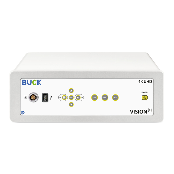
Page 11: Control Elements / Connections
Control elements / Connections Front view Note labeling style for the front view: „ “ • Device without archiving option • Device with archiving option... - Page 12 Rear view Note labeling style for the front view: „ “ Camera head...
- Page 13 Description of the control elements and connections The plug of the camera cable is connected to this socket.The plug has an anti-twist safe- Camera cable: guard, so that the plug can only be plugged in one position. Attention! Use only the supplied camera head and cable! This USB-interface it‟s for connecting the device with USB flash drives to record data.
- Page 14 By pressing this button videos can be stored (MPEG-4) on the connected USB flash drive or Video capture (optional) within the menu settings can be made. / Scroll: • If you want to record a portion of the video, press this button once to start recording. The storage process is signaled with a flashing “REC”...
-
Page 15: Operation
Operation Start up After all cable connections have been made, the camera can be put into operation. Switch on the camera by using the mains switch on the rear. The green light in the switch lights up. Note: When the “POWER OnSTART” function is activated, the device switches directly to the operating mode. (See also chapter: “Menu settings - Options - POWER OnStart”) Otherwise, the device is now in standby mode. -
Page 16: Menu Settings
The following user profiles are available as standard settings (factory default settings): · Lap 10mm: Standard setting for laparoscopy with 10mm endoscopes · Lap 10mm enh R Y: Standard setting for laparoscopy with 10mm endoscopes, enhancement function for contrast sprea- ding in the red / yellow area, improved contrast for visualizing the vessels ·... - Page 17 Submenus: Illumination (Main menu item 1) This menu item offers the user the possibility to individually adjust the illumination of the camera image. → BRIGHTNESS The brightness of the overall image can be regulated under this menu item. As shown in the picture above, the current value is visualized by a slider and a numerical value.
-
Page 18: Shutter Mode
GAMMA Changing the GAMMA value →→ DETAIL The detail contrast can be defined under this menu item. →→ BAND Determining the emphasis between coarser and finer image stuctures →→→ LEVEL Edge enhancement to enhance the sharpness of the image →→→ SHUTTER MODE Setting Shutter-Mode: Manual (1/60…1/10.000) / Automatic →→... - Page 19 Color (Main menu item 2) In this menu, the total color saturation and the intensity of the individual colors can be set. A color bar pattern can also be inserted (4 COLOR BAR) for test purposes. → Saturation Use this control to adjust the color saturation. →→...
- Page 20 Area (Main menu item 3) Under this menu item, the measurement field for the bright- ness control can be set. → Option (Main menu item 4) → LANGUAGE In this menu the desired language of the menu can be se- lected.
-
Page 21: Info Screen
INFOSCREEN The Infoscreen displays current status information →→ FACTORY DEFAULT By activating the “Reset” point, all parameters are reset to the factory settings and the system is “rebooted”. This is characterized by a uniform flashing of the button lighting and lasts approx. -
Page 22: Power Onstart
POWER OnSTART In the “POWER OnStart” menu you can specify whether the device starts directly in the operating mode when it is swit- ched on with the mains switch Function: „ON“ - the device starts directly in the operating mode when the mains switch is switched on Function: “OFF”... -
Page 23: Video Format
VIDEO FORMAT Depending on the monitor, the setting of the video resolu- tion can be made here. · HDMI 1: 4K resolution · HDMI 2: FullHD resolution · SDI 1: 4K resolution · SDI 2: FullHD resolution →→ Abbreviations / method of image composition: p: progessive i: interlaced Sa: Sample interleave... -
Page 24: Image Enhancement
SDI 1: Selecting the color space between BT.2020 or BT.709.5 →→→ Head Center: Adjusting the image orientation →→ IMAGE ENHANCEMENT In various modes image enhancements can be made. The mode that is active in the userpreset flashes. If a mode is changed, it is automatically activated. - Page 25 COLOR ENHANCEMENT RED & YELLOW Color adjustment in the red & yellow area →→→ COLOR ENHANCEMENT YELLOW Color adjustment in the yellow area →→→ SMOKE CORRECTION →→→ SHADOW REDUCTION →→→ OVER EXPOSURE REDUCTION →→→...
-
Page 26: Frame Rate
Record Board Adjustment (optional) This menu item various parameters associated with the sto- rage of images or videos can be adjusted. The detailed settings can then be made in the menus below. →→ RESOLUTION Image resolution in recording mode (1920x1080; 1280x720; 640x360;... -
Page 27: Button Allocation
FORMATING Format the connected USB storage media. The “Format” message flashes during the formatting process. If the format- ting is completed successfully, the message “OK” appears. →→→ Optional Features • Connecting USB flash drives Use the USB port (Type A) on the front side of the device for connecting external USB storage devices (flash drives). When a USB device is connected to this interface, the message “USB”... - Page 28 · F11: Bildspeicherung · F12: Videoaufnahme (Start/Stop) · BREAK: FREEZE (freeze frame) · PRTSC: REMOTE (ext. switching contact) · ESC: QUIT Ende à Menu or OSD · PG-UP: ZOOM+ · PG-DW: ZOOM- · STRG+ALT+S: WHITE SHADING · STRG+ALT+P/B: BLEMISH DAT/COM: ·...
-
Page 29: Service Interval
Service instructions General maintenance and repair instructions The information contained in this chapter is only intended for properly trained personnel, which is proficient in the required knowledge and security arrangements for the repair of electronic equipment. The manufacturer assumes no li- ability for repairs and modifications carried out by unauthorized personnel. - Page 30 Cleaning / Desinfection • Housing: Attention! Disconnect the main power plug prior to beginning the cleaning/disinfection! All external surfaces of the device are resistant to all common cleaners and disinfectants, so that these may be used without restrictions. For the application of cleaning and disinfecting liquids, a soft cloth or blotting paper should be used to avoid scratching the surface and to better dispense and distribute the liquid.
-
Page 31: Troubleshooting
Troubleshooting In the case of a malfunction of the device, please try localizing the error source and repairing it yourself by using the table below, before you return the unit to the manufacturer for repair. Error Description Possible Causes Remedy No image on the monitor Power cord not connected Connect power cord... - Page 32 Picture too bright Parameter brightness (OSD) set at maxi- Decrease parameter brightness Measuring range for brightness control Adjust parameter Area (OSD) is too small Monitor settings not optimal Verify / correct the monitor settings Shutter defective Send unit for repair Image blurred Lens fogged Clean / replace lens...
-
Page 33: Specifications
Specifications Technical data General data Line voltage: 100-240 VAC | 50-60 Hz Power requirements: 60 VA Mains fuses: Fuses, 5x20mm, inert 3,15 AH, 250V with high switching capacity (Ia = 1500 A) Dimensions (WxHxD): Control unit: 360 x 125 x 351 mm (WxHxD) Camera head: Ø... - Page 34 Video format: HDMI output: 3840x2160/59.94p, 3840x2160/50p, 1920x1080/59.94p, 1920x1080/59.94i, 1920x1080/50p, 1920x1080/50i SDI output: 3840x2160/59.94p, 3840x2160/50p, 1080/59.94p, 1080/59.94i, 1080/50p, 1080/50i Archiving: 1 x USB (A) Other connections: 1 x USB (A) (USB-keyboard) 1 x Remote IN (footswitch) 2 x Remote OUT (video printer, video recorder,…) 2 x RJ45 (service interface) Classification / Conformity Safety class (EN 60601-1)
-
Page 35: Electromagnetic Compatibility
Annex Electromagnetic compatibility • The present device corresponds to the following standard: IEC 60601-1-2 • Precautionary measures Electro-medical devices are subject to special precautionary measures concerning electromagnetic compatibility (EMC). This device is to be used for the purposes described in the operation manual and has to be installed, set up, and operated in com- pliance with the EMC guidelines. - Page 36 • Manufacturer’s declaration – Electromagnetic immunity: Ful- Immunity tests Test level Electromagnetic environment – Guidelines filled Electrostatic discharge (ESD) ± 2; 4; 6; 8 kV Floors should be made of concrete or wood according to IEC 61000-4-2 or covered with ceramic tile. If the floor is Contact discharge covered with synthetic material and offers no ESD protection, the relative humidity...
- Page 37 Fast transient electrical dis- ± 2 kV 100 kHz supply lines turbances/bursts according to ± 1 kV 100 kHz signal and data IEC 61000-4-4 lines Surges according to IEC ± 0,5 kV, ± 1 kV 100 kHz (line 61000-4-5 to line) ±...
-
Page 38: Maintenance Report
Maintenance report User Address Serial-No.: Servicing check up Name Date Signature... - Page 39 Icons (Instruction manual) Attention, important information! Service information Symbols (Medical device) Follow instructions for use (EN ISO 7010-M002) Follow instructions for use (EN ISO 15223-1, 5.4.2) Application part type: BF (IEC 60417-5333) - Connection Connection for potential equalization (IEC 60417-5021) - Connection Grounding (IEC 60417-5021) Corresponds to the EU regulation 2017/745, annex V Do not dispose of with household waste (ElektroG / WEEE 2012/19/EU)
- Page 40 ILO electronic GmbH Carl-Zeiss-Str. 3 25451 Quickborn / Germany Phone: +49 (0) 4106-7758-0 www.ilo.com info@ilo.com...
Need help?
Do you have a question about the 4K UHD VISION (K) and is the answer not in the manual?
Questions and answers