
Related Manuals for PIKODER SPE LAN

Summary of Contents for PIKODER SPE LAN
- Page 1 PiKoder /SPE LAN Development board Building instructions Version 1.0 As of 04/2024 Gregor Schlechtriem webmaster@pikoder.de www.pikoder.de...
-
Page 2: Table Of Contents
Development board PiKoder /SPE LAN construction instructions Table of contents General information Kit scope and aids Construction Equipping the angled pin strip ................7 Equipping the controller ..................7 ............................7 Assembling the socket strips................. 8 Installation Fehler! Textmarke nicht definiert. - Page 3 General information With the PiKoder /SPE LAN development board you control a PPM signal via LAN. Typical applications use a PC to operate a remote control transmitter remotely and with a joystick. Before you start building the development board for the PiKoder/SPE LAN read these instructions through to the end.
- Page 4 Development board PiKoder /SPE LAN construction instructions...
-
Page 5: Kit Scope And Aids
In addition, the following tools are required to assemble this kit: 1. Electronic soldering iron with a fine tip 2. Electronic soldering tin 3. Side cutters To put the PiKoder/SPE LAN into operation you also need: 1. Micro USB cable 2. Ethernet patch cable 3. 5 Volt power supply... - Page 6 Development board PiKoder /SPE LAN construction instructions...
-
Page 7: Construction
Construction The following sections describe the assembly of the missing components on the circuit board. All components are located on the assembly side and the assembly process itself is supported by the assembly imprint on the circuit board. The order of assembly depends on the height of the components - the general rule is that the flattest components are assembled first. -
Page 8: Assembling The Socket Strips
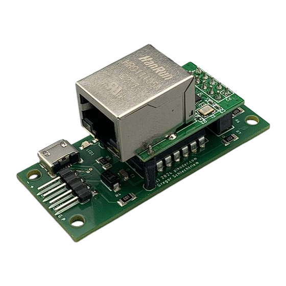
Development board PiKoder /SPE LAN construction instructions Assembling the socket strips Finally, the remaining socket strips have to be fitted, which will then accommodate the Ethernet converter . For alignment, the socket strips are plugged into the con- verter and then placed onto the circuit board. If you care-... -
Page 9: Ppm And Connection Settings
The required software modules are available to download free of charge on the In- ternet. PPM and connection settings In the first step, you make the PPM and connection settings of the PiKoder via the USB port on the base circuit board. In addition to a suitable USB cable, you also need the “... - Page 10 Development board PiKoder /SPE LAN construction instructions Please change the baud rate to 115200 and then press the “Save Parameters” button. This completes the setting of the PiKoder/SPE and you can remove the USB cable.
-
Page 11: Setting The Ethernet Adapter
Setting the Ethernet adapter The following section describes the necessary settings of the Ethernet adapter . First connect your PiKoder/SPE LAN to a 5 Volt power source as shown in the following image. To parameterize the Ethernet adapter, use the manufacturer's configuration pro- gram ETH-002_configuration.exe , which you... - Page 12 Development board PiKoder /SPE LAN construction instructions If you press the “Search” button, your adapter will be found and displayed. If you now double-click the line with your adapter, the settings will be loaded.
- Page 13 Please make the following adjustments (see below): IP address: please assign the adapter an IPv4 address within your network Gateway: please adjust according to the assigned IP address Mode: switch to TCP_SERVER Baud: increase to 115200...
-
Page 14: Joystick Ui For Windows
Microsoft Store. Install the app, connect your PiKoder to the 5 volt power supply and your network and then start the app. First, you will be asked to enter the IPv4 address of the PiKoder that you assigned in the previous step into the app. - Page 15 The app works with the standard frequency for PPM of 50 Hz (“Rate set ”). This means that an update is sent to the PiKoder every 20 ms . The time that the program needs to calculate the current channel values is shown in the “ Actual processing time”...
-
Page 16: Connections
Connections... - Page 17 Schematics...
Need help?
Do you have a question about the SPE LAN and is the answer not in the manual?
Questions and answers