Table of Contents
Advertisement
Quick Links
Advertisement
Table of Contents

Related Manuals for Sherpa 100 ECO HYPAC Narrow

Summary of Contents for Sherpa 100 ECO HYPAC Narrow
-
Page 2: Preface
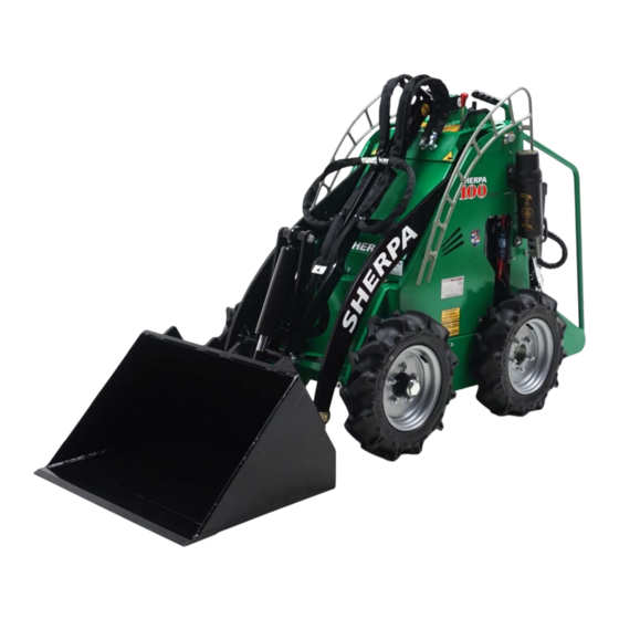
Preface This operating manual is for the SHERPA 100 ECO HYPAC Narrow. In order to get the most out of this SHERPA mini-loader, it is imperative that you read this manual in its entirety so you understand how the machine works and the types of work it is designed to perform. -
Page 3: Table Of Contents
Contents Preface ......................1 Introduction ....................6 Description of the mini skid-steer ............7 1.1. Operation ......................... 7 1.1.1. Design ............................7 1.1.2. Drive system ..........................7 1.2. Technical data and tipping loads ................... 8 1.2.1. Technical data..........................8 1.2.2. Tipping loads.......................... - Page 4 3.4. Machine pictograms ..................... 25 3.4.1. Mini-loader ..........................25 3.4.2. Traction battery ........................29 Operation ....................30 4.1. Control elements ......................30 4.1.1. Drive controls ........................... 30 4.1.2. Braking ............................. 32 4.1.3. Lifting control..........................32 4.1.4. Tilting control..........................32 4.1.5. Auxiliary lever........................... 33 4.2.
- Page 5 6.5. Yearly ..........................51 6.5.1. Check isolation resistance ....................... 51 6.6. Maintenance schedule for the mini skid-steer ............52 6.7. Every 10 operating hours or daily ................53 6.7.1. General ............................ 53 6.7.2. Check for leaks in the hydraulic drive systems ................ 53 6.7.3.
- Page 6 10.6. EG declaration & checklist ..................67...
-
Page 7: Introduction
Introduction This operating manual is for the SHERPA 100 ECO HYPAC Narrow, which is manufactured by SHERPA mini-loaders in Nistelrode, the Netherlands. This manual contains everything you need to know about the operation, maintenance and safe use of the machine. Dangerous situations are pointed out and warnings issued against unsafe use, working in unsafe conditions and using the machine for purposes other than those intended by the manufacturer. -
Page 8: Description Of The Mini Skid-Steer
1. Description of the mini skid-steer 1.1. Operation 1.1.1. Design The mini skid-steer consists of a single frame. The frame has lift arms to which tools and implements can be attached. Examples of such tools and implements are a bucket, fork or broom. Other tools and implements are available. -
Page 9: Technical Data And Tipping Loads
1.2. Technical data and tipping loads 1.2.1. Technical data Engine: Manufacturer: Sevcon Type: HypAC Capacity (kW/pk): 1.5/2 Max. speed (rpm): 1800 Tuned speed (rpm): 1800 System: Brushless DC motor Coolant: Air cooled Drive system: Hydrostatic through 2 hydraulic wheelmotors/ 2 front wheels through chain transmission Speed (km/h): 0-3.5 (proportional) Capacity data:... -
Page 10: Tipping Loads
1.2.2. Tipping loads The tipping loads are specified in the below table for each type of bucket and fork. The loads are based on standard LCD sizes in accordance with NEN-EN 474-3. Explanation: Distance from the load's center of gravity to the tool's mounting point (mounting plate). Unit of measure: MM Weight of the load Unit of measure: KG Nominal working loads:... -
Page 11: Operating And Control Area
1.3. Operating and control area The operating location of the mini-skid steer loader is behind the platform. -
Page 12: Explanation Of The Identification Signs
1.4. Explanation of the identification signs 1.4.1. Manufacturer's plate Explanation of the information on the manufacturer's plate Manufacturer Name and address of manufacturer Type The type number or description Serial no. Serial number Weight Weight [kg] Year Year of manufacture Power Capacity [kW] 1.4.2. -
Page 13: Purpose
2. Purpose 2.1. Intended use 2.1.1. Types of work The mini skid-steer can be used to perform the following types of work: Moving, “lifting” and “tipping” of sand, earth, gravel or other loose material. Moving rocks. Moving full pallets. ... -
Page 14: Tools Or Equipment
2.2. Tools or equipment A shovel, fork or other attachment tool that is mounted on the mini skid-steer must not exceed the volume and load capacity of the mini skid-steer stated in section 1.2.2. (Tipping loads), and it has to be anounced in the enclosure: “Attachments & options”. It is permitted to use hydraulic tools providing the total hydraulic working load is lower or equal to the maximum allowable hydraulic load. -
Page 15: Safety And Warnings
Changes and adaptations to the function, operation or principle of the mini skid-steer may not be made without permission from SHERPA mini-loaders and are the full responsibility of the person who makes them. This also applies to the safety features and the hydraulic components used in the machine. -
Page 16: Basic Safety Definitions
3.2. Basic safety definitions 3.2.1. Organizational measures Operating manual The manual for the mini skid-steer must be on the mini skid-steer at all times and must always be within the operator's reach. Pictograms You must observe the warnings and instructions that are indicated by the pictograms on the mini skid-steer. -
Page 17: Safety Regulations For The Operator
Work lights A machine that is not equipped with work lights may not be used in the dark. Public roads The mini skid-steer does not meet road traffic regulations and may therefore not be driven on public roads. Ambient temperature The ambient temperature must be between -20°C and +30°C. - Page 18 (driving with load) (driving without load) Driving with load When driving with a raised load, the speed must be as low as possible to minimize the risk of toppling over. Always drive with the load's center of gravity as low as possible. This reduces the risk of toppling over.
- Page 19 It is prohibited to transport people on the mini skid-steer The operator of the mini skid-steer may not, under any circumstances, transport people at the front or the back of the mini skid-steer. It is prohibited to lift people with the mini skid-steer The operator of the mini skid-steer may not, under any circumstances, lift people with or without the attachment tools or other equipment.
-
Page 20: Safety During Use
3.2.3. Safety during use Starting the mini skid-steer The engine may not be started until the operator has checked that the mini skid-steer will not move when started. To avoid operating errors, the operator must familiarize himself/herself with the way the mini skid-steer works. -
Page 21: Safety Concerning The Traction Battery
3.2.5. Safety concerning the traction battery Before servicing the traction battery carefully read the manual of the manufacturer of the battery. Carry out maintenance (filling, charging, etc.) always with the engine switched off. The ignition key should be removed and the traction battery should be disconnected. Only service the battery under the supervision of trained personnel. - Page 22 First aid for accidents with battery fluid If inhaled: Remove victim to fresh air. Keep victim at rest in a position comfortable for breathing. If necessary, administer oxygen and take the victim to hospital immediately. If in eyes: Rinse cautiously with water for several minutes. Remove contact lenses if present and easy to do.
-
Page 23: Safety Regarding The Charging/Use Of The Traction Battery
3.2.6. Safety regarding the charging/use of the traction battery Before you use the machine carefully read the safety data sheets from the manufacturer of the battery and the charger. Explosion hazard During and shortly after charging the battery electrolytic gas comes free, an extremely explosive gas mix. -
Page 24: Transporting, Hoisting And Lifting Safety
Never try to repair or seal hydraulic hoses or couplings while the machine is running or when the hydraulic drive system is under pressure. The liquid has such a high pressure that the hydraulic oil can easily penetrate the skin and cause serious injuries. -
Page 25: Guarantee
SHERPA mini-loaders. believes that the machine and/or accessories have been neglected or carelessly and unprofessionally used, treated and/or maintained, and/or there is evidence of abnormal wear and tear;... -
Page 26: Machine Pictograms
3.4. Machine pictograms 3.4.1. Mini-loader The following pictograms can be found on the mini skid-steer: These pictograms draw the operator’s attention to the potential risks and hazards associated with using the mini skid-steer. The pictograms may not be removed. Pictograms that are damaged or have become unreadable must be replaced. - Page 27 Warning!! Read the manual before proceeding Risk of tipping, When driving without load Check wheelnuts The electric motor has an IP class 54 (splash waterproof) Do not spray on the electrical parts with a high pressure cleaner...
- Page 28 Various warnings for which no icon is present on the machine (* Text according as below)
- Page 29 (*Test safety label) Venting hose Always make sure that the venting hose is free from dust and dirt. When the battery is being charged in a confined space an extension tube must be coupled which is conducted to an open and/or adequately ventilated area. Make sure the venting hose has no obstructions in any way!
-
Page 30: Traction Battery
3.4.2. Traction battery The following pictograms are place on the traction battery. These pictograms warn the user for potential risks or hazards arising from the use of the traction battery. The pictograms may not be removed. If the icons are damaged or have become illegible they should be replaced. Pictogram Explanation Place on the traction battery... -
Page 31: Operation
4. Operation 4.1. Control elements There are four spring-loaded levers at the front of the mini skid-steer. 4.1.1. Drive controls The left red lever (1) operates the wheels on the left side and the right red lever (2) operates the wheels on the right side of the mini skid-steer. - Page 32 The mini skid-steer is steered by pushing or pulling one lever further forward or backward than the other. To turn the machine to the left while driving: To turn the machine to the right while driving: forwards: Push the right lever further forward forwards: Push the left lever further forward than the left lever.
-
Page 33: Braking
4.1.2. Braking Bring driving levers slowly to center position. Be careful when you stop. The machine can topple over if a bucket or other attachment tool is still raised. Drive slowly and make steady and flowing motions when driving with raised lift arms. All new operators must first work with the machine in an open space until they master the steering and driving. -
Page 34: Auxiliary Lever
4.1.5. Auxiliary lever The auxiliary lever operates the hydraulic drive system for the attachment tools. The lever has three positions: Center position: hydraulic drive system for the tools is inactive Downward position: oil flows to the left coupling ... -
Page 35: Operating The Engine
4.2. Operating the engine 4.2.1. Starting the engine Insert the plug (1) into the socket on the left backside of the machine. Insert the key (2) in the mass switch and turn it clockwise. The battery level indicator (3) lights up and shows the remaining capacity of the battery. -
Page 36: Loading And Unloading
4.3. Loading and unloading Follow the below instructions when loading and unloading: Stability Take the condition of the terrain into account (holes, uneven, swampy). When driving with a raised load, the speed must be as low as possible to minimize the risk of toppling over. - Page 37 Capacity Observe the allowable machine capacity indicated in section 1.2.2. (Tipping loads). Overloading the machine can have serious implications, such as the machine toppling over. Ending work, taking a break The attachment tools must be lowered to the ground when the mini skid-steer is not in use (do not park on a slope).
-
Page 38: Attaching And Detaching Attachment Tools
4.4. Attaching and detaching attachment tools 4.4.1. Requirements for attachment tools Attachment tools Only attachment tools with a CE-mark may be mounted on the mini skid-steer. It is prohibited to use attachment tools with an allowed mechanical and/or hydraulic load or capacity that is higher than that of the mini skid-steer. -
Page 39: Detaching Tools
Check Always check that the tool is fastened properly. A tool that is not properly fastened can cause serious damage! 4.4.4. Detaching tools To detach a tool, proceed as follows: Slide the two lock pins in the “open” position. ... -
Page 40: Use Of The Traction Battery
5. Use of the traction battery 5.1. General Always load the traction battery and then refill the electrolyte (battery). Before performing maintenance work (filling, charging, etc.), always switch off the engine, remove the key from the grounding switch and disconnect the traction battery. -
Page 41: Charging Traction Battery
5.2. Charging Traction battery The battery may only be charged with direct current. All of the charging systems that meet Standard DIN 41773 and 41774 can be used. Connect the battery only to the matching charger with the correct setting to prevent overcharging it, sharp temperature increases, excessive gas formation and the overflow of electrolytes. - Page 42 When connecting the charger to the power supply (230 V/400 V AC), the power socket must be protected with a suitable slow blow fuse or K type fuse. All chargers come with a transformer with nominal voltage Uo /U (230 V/400 V) and have connections for +6%/-6%, -10%.
-
Page 43: Refilling
5.3. Refilling The electrolyte level must be checked after charging. If necessary, top up with distilled water. The traction battery is equipped with an automatic filling system. A central filling system quickly fills all of the cells at the same time. The filling system is time-saving because a float ensures that each cell is automatically filled to the correct level. - Page 44 Connect filling tank The filling hose (1) is located at the traction battery on the right side of the mini-loader Connect the hose on the refill vat to the connection on the traction battery (2) Open the filling tap (3) on the refill vat. Allow the refill tank until the flow indicator (4) stops running.
-
Page 45: Changing Traction Battery
5.4. Changing Traction battery The mini-skid loader is equipped with a quick change system for the traction battery. Remove the hairpin springs (1) from the latches. Fold down the the latches (2) so that the bracket comes loose from the machine. - Page 46 (*availiable as an option) Battery change truck and storage refill station.
-
Page 47: Maintenance
6. Maintenance 6.1. General The mini skid-steer must be maintained periodically, i.e. the machine and the parts cleaned, hinging parts lubricated, the oil changed and so forth. Maintaining the machine as recommended prevents failures and extends the mini skid-steer's service life. General safety rules for maintenance Work on the mini skid-steer may only be carried out by trained staff. -
Page 48: Hour Counter & Battery Level Indicator
6.1.2. Hour counter & battery level indicator The hour counter and battery level indicator (1) are located on top of the control panel. On the small screen you can see the total working hours of the machine. The battery level indicator points out how many hours can be worked with the machine. -
Page 49: Maintenance Schedule For Traction Batteries
6.2. Maintenance schedule for traction batteries Task See sector. Daily Half-yearly Yearly Charging 6.3.1 Refilling distilled water 6.3.2 Check specific gravity and 6.4.1 temperature Check isolation resistance 6.5.1 Environment Environmentally harmful substances (e.g. liquids and lubricants) must be stored and disposed of in accordance with the applicable regulations. -
Page 50: Daily
6.3. Daily 6.3.1. Charging The Battery should be recharged after every discharge. See section 5.2. (Charging). 6.3.2. Refilling distilled water The electrolyte level should be checked after every recharge of the battery. If necessary, top up with distilled water. Battery recharge after a discharge. See section 5.3. -
Page 51: Half-Yearly
6.4. Half-yearly 6.4.1. Check specific gravity and temperature From all cells (when the charger is switched on) the tension, specific gravity, and the temperature of the electrolyte must be measured and written down. Please note these data at the beginning and at the end of the recharging process. A battery check sheet is provided for these data. -
Page 52: Yearly
6.5. Yearly 6.5.1. Check isolation resistance According to the VDE 0117 norm the isolation resistance of the battery and/or machine must be checked at least once a year by an expert. This expert will measure the battery according to the DIN 43539/1 norm. The measured insulation resistance of the battery should, according to the Standard DIN VDE 0510/3 norm, not be lower than 50ohm per volt nominal battery voltage. -
Page 53: Maintenance Schedule For The Mini Skid-Steer
6.6. Maintenance schedule for the mini skid-steer 10 operating hours 50 operating hours 200 operating 600 operating 1000 operating Task section (daily) (monthly) hours (half-yearly) hours (yearly) hours Check for leaks in the 6.7.2 hydraulic drive systems ... -
Page 54: Every 10 Operating Hours Or Daily
6.7. Every 10 operating hours or daily 6.7.1. General General safety rules for maintenance Work on the mini skid-steer may only be carried out by trained staff. Before working on the mini skid-steer, make sure it is standing on a level and solid surface. -
Page 55: Check The Hydraulic Oil Level
6.7.3. Check the hydraulic oil level The oil level is checked with a dipstick (1) that is at the front of the machine on the hydraulic tank. The level must reach the notch (2) on the dipstick. All of the cylinders must be retracted when checking the oil level. -
Page 56: Every 50 Operating Hours Or Monthly
6.8. Every 50 operating hours or monthly 6.8.1. General General safety rules for maintenance Work on the mini skid-steer may only be carried out by trained staff. Before working on the mini skid-steer, make sure it is standing on a level and solid surface. -
Page 57: Check Tire Pressure
6.8.3. Check tire pressure The correct pressure for the standard tires is (type 4.00 x 10) 2.5 bar. Check the tire pressure daily for the first 50 operating hours. The instructions are provided below. 6.8.3.2. Check If the pressure is low, increase the pressure to the level indicated above. Remove the protection cap from the valve. -
Page 58: Every 200 Operating Hours Or Half-Yearly
6.9. Every 200 operating hours or half-yearly 6.9.1. General General safety rules for maintenance Work on the mini skid-steer may only be carried out by trained staff. Before working on the mini skid-steer, make sure it is standing on a level and solid surface. -
Page 59: Check/Adjust Chain Tension
6.9.4. Check/adjust chain tension Before working on the mini skid-steer, make sure it is standing on a level and solid surface. Work may only be carried out with the engine switched off and a disconnected traction battery. Check the chain tension through the inspection hole in the chain guard between the wheels. You must remove the wheels and the chain guard to adjust the chain tension. -
Page 60: Check/Replace Pins And Bearing Bushes
6.9.5. Check/replace pins and bearing bushes Before working on the mini skid-steer, make sure it is standing on a level and solid surface. Work may only be carried out with the engine switched off and a disconnected traction battery. The hinge points on the mini skid-steer are equipped with pins and high-quality plastic bushes. These parts are sensitive to wear from sand, dust and dirt. -
Page 61: Every 600 Operating Hours Or Yearly
6.10. Every 600 operating hours or yearly 6.10.1. Change the wheels When mounting a wheel, fasten the wheel nuts a few turns. Then tighten the nuts in a criss-cross pattern until you reach the correct torque. -
Page 62: Every 1000 Operating Hours
6.11. Every 1000 operating hours 6.11.1. Change hydraulic oil The hydraulic drive system should only be opened in a clean environment! Work may only be carried out with the engine switched off and a disconnected traction battery. Work on the hydraulic drive system may only be carried out when the system is not under pressure. -
Page 63: Transport And Storage
7. Transport and storage 7.1. Transport 7.1.1. Transportation on a trailer The mini-loader must be driven backwards on a trailer due to the risk of tipping over. The driver should be aware of the risk of tipping over when no attachments are mounted on the machine. -
Page 64: Lifting
7.1.3. Lifting The machine's weight is 759kg, without attachment tools. Only use material with sufficient hoist and lifting capacity. Only use material that is sufficiently strong and of good quality. Never stand under the load you are hoisting or lifting! The mini skid-steer may be lifted only at the following point (indicated by the sticker): When securing the machine (e.g. -
Page 65: Storage
7.2. Storage 7.2.1. Preparing the machine for storage Storage temperature The storage temperature must be between -20°C and +30°C. Storage outside these temperatures can damage the machine. Proceed as follows if the machine will be stored for a longer period: ... -
Page 66: Driving On Hilly Terrain And Slopes
8. Driving on hilly terrain and slopes When driving on hilly terrain or slopes, you must pay attention to the angle of incline and always drive with the load's center of gravity as close to the ground as possible. A sharp angle of incline affects the machine's stability. -
Page 67: Failures
9. Failures 9.1. Melting fuse table Value Function Place (Amp) Inside left panel Main fuse Fuse buzzer Inside left panel Before you replace the fuse first eliminate the cause of the malfunction. -
Page 68: Appendices
10. Appendices 10.1. Hydraulics diagram Hydraulics diagrams are provided on request. 10.2. Electrical circuit diagrams Electrical circuit diagrams are provided on request. 10.3. User manual charger See the user manual of IEB which is also supplied. 10.4. Operation & maintenance instructions for traction batteries See the instructions of “Batterij Aandrijf Techniek B.V which is also supplied.
Need help?
Do you have a question about the 100 ECO HYPAC Narrow and is the answer not in the manual?
Questions and answers