Table of Contents
Advertisement
Quick Links
Operating Instructions
Included Installation Instructions
Microphone
WX-CM470P
Model No.
Before attempting to connect or operate this product,
please read these instructions carefully and save this manual for future use.
The model number is abbreviated in some descriptions in this manual.
PUQX1033ZA
WX-CM470P_PUQX1033ZAV1_OI_en.indd
1
2021/10/27
11:20:08
Advertisement
Table of Contents

Related Manuals for Panasonic WX-CM470P


Summary of Contents for Panasonic WX-CM470P
- Page 1 Operating Instructions Included Installation Instructions Microphone WX-CM470P Model No. Before attempting to connect or operate this product, please read these instructions carefully and save this manual for future use. The model number is abbreviated in some descriptions in this manual.
- Page 2 ENGLISH VERSION WARNING: ● The apparatus should not be exposed to dripping or splashing and that no objects filled with liquids, such as vases, should be placed on the apparatus. ● All work related to the installation of this product should be made by qualified service personnel or system installers.
-
Page 3: Table Of Contents
Contents Important safety instructions......................4 Limitation of liability ........................5 Disclaimer of warranty ........................5 Precautions............................ 6 Precautions for installation ......................8 Preface ............................9 Major operating controls and their functions................10 Installing ............................12 Connecting to the center module....................17 Settings on the center module ..................... -
Page 4: Important Safety Instructions
Important safety instructions 1) If the units fall, it can cause serious damage to persons or properties. 2) Read these instructions. 3) Keep these instructions. 4) Heed all warnings. 5) Follow all instructions. 6) Do not install near any heat sources such as radiators, heat registers, stoves, or other appa- ratus (including amplifiers) that produce heat. -
Page 5: Limitation Of Liability
IMPROVEMENTS OF THIS PUBLICATION AND/OR THE CORRESPONDING PRODUCT (S). Disclaimer of warranty IN NO EVENT SHALL Panasonic Corporation BE LIABLE TO ANY PARTY OR ANY PERSON, EXCEPT FOR REPLACEMENT OR REASONABLE MAINTENANCE OF THE PRODUCT, FOR THE CASES, INCLUDING BUT NOT LIMITED TO BELOW:... -
Page 6: Precautions
Precautions Refer installation work to your dealer. When installing the product, use the Skill and experience are required for provided screws and nuts. installation to avoid risk of fire, electric shock, Failure to do so may cause the product to fall, injury and damage. - Page 7 Do not replace parts in the state of the Be sure to use the product in combination product mounted. with the products for the Panasonic There is a risk of parts falling, resulting in Wireless Communication System. accidents. Otherwise fire or electric shock may result.
-
Page 8: Precautions For Installation
Precautions for installation Warning ● Be sure to contact your dealer for installation. ● Before installing, turn off the center module connected with this product. In addition, be sure to read “Precautions” carefully and follow the Instructions (page 6, 7). Moreover, be sure to read operating instructions of the connecting product as well. -
Page 9: Preface
● This product is the Microphone designed for the exclusive order posts to be used in combination with the Panasonic Wireless Communication System. ● While the slim and small-sized shape is compatible with the installation on most of the order posts, the product has accomplished the clear sound which can achieve the communication even under the engine noise. -
Page 10: Major Operating Controls And Their Functions
Major operating controls and their functions Main unit Sound apertures Input wire Accessories ● Screw for installation (x2) They are the mounting screws (M5 x 20) for the order post. ● Retaining nut (x2) Nuts (M5) for installing on the order post. ●... - Page 11 ● Foam 1, Foam 2 for installation (Shock-absorbing material used for the packing of this product) These foams are used for the prevention of sound leakage from/to the front side of the main unit to/from the interior of the order post and the reduction of transmitted vibration from/to chassis of order post.
-
Page 12: Installing
Installing „ Important notice Caution for safety ● This product is only installable inside the order post or similar structure ,must not exposed outside or sunshine directly. In addition, safety measures such as safety wires are not provided with the product. Do not install the product in places of 1.5 m {5 feet} or higher when the product is installed inside the order post or similar structure. - Page 13 ● Make the opening of the order post wider than the sound apertures of the Microphone so that the entire sound apertures can be set in the opening. ● Expose the sound apertures of the Microphone from the opening of the order post. When covering the opening with a mesh net or punching metal sheet, select the one with relatively high aperture ratio.
- Page 14 „ Installation of the Microphone ● These servicing instructions are for use by qualified personnel only. To reduce the risk of electric shock do not perform any servicing other than that contained in the operating instructions unless you are qualified to do so. Refer all servicing to qualified service personnel.
- Page 15 Installation by tightening the screws through front panel of order post ● Make two holes (ø6 mm {ø1/4 inches}) for the mounting screws near the front opening of the order post. Refer to the appearance diagrams “Dimension for settlement” on page 22 for details on the positions and dimensions of the holes.
- Page 16 Example of installation using the provided Foam 1 and 2 Before connecting to the center module and performing wiring, pass the cable through the hole on Foam 1. 1. Mount the unit onto Foam 1, and install them into the order post. ●...
-
Page 17: Connecting To The Center Module
C Connect the Lane A mic input “GND” wire to the “GND (Black)” wire of this unit. ● Use soldering, crimping sleeves, etc. to connect securely. Microphone WX-CM470P Speaker (8 Ω) A Connect HOT wires to each other B Connect COLD wires to each other... - Page 18 0.8 mm and 0.1 mm (AWG18-AWG28). ● When using for Microphone, use a shield cable meeting the above conditions. ● Perform wiring while matching the polarities correctly. WX-CC411BP WX-CM470P WX-CC412BP Lane A ← Connect → Red Lane B –...
-
Page 19: Settings On The Center Module
Settings on the center module WX-CM470P needs to be selected in the settings of the Center Module (WX-CC411BP, WX-CC412BP). (Either WX-CM470P or WX-CS560 can be selected.) Electret Microphone : Using WX-CM470P. Microphone/Speaker : Using WX-CS560. Default setting: Electret Microphone: * Lane B is not displayed when using WX-CC411BP. -
Page 20: Troubleshooting
Troubleshooting Check the following before requesting repair. Consult your sales shop if these measures do not resolve a problem, if symptoms not listed here occur, or if you have a question related to engineering. Reference Symptom Cause/solution pages ● Are they wired correctly? Confirm that the wiring is connected Sound from the correctly. -
Page 21: Specifications
Specifications Sensitivity: –10 dB (0 dB=1 V/Pa, 1 kHz, Typical) Frequency response: 100 Hz - 8000 Hz (–10 dB, Typical) • Miscellaneous Input/Output: Approximately 1000 mm {39-3/8 inches} two core shielded wire Outer diameter: ø3 mm {ø0.11 inches} Inner wire: AWG24 Inner sheath color: Red: + White: –... -
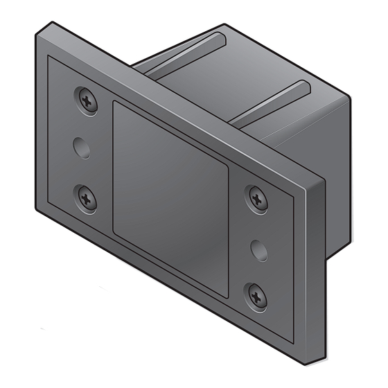
Page 22: Appearance
Appearance Dimension for settlement Unit: mm {inches} 62 (2-7/16) 94 (3-45/64) *42 (1-21/32) ● When attaching the provided gaskets on the units, add 2 mm {5/64 inches} to the dimension marked with “*” so that front panel of units stick to the mounting surface of the order post. WX-CM470P_PUQX1033ZAV1_OI_en.indd 2021/10/27 11:20:10...
Need help?
Do you have a question about the WX-CM470P and is the answer not in the manual?
Questions and answers