Table of Contents
Advertisement
Quick Links
GF-1 1 200-A A
Model
™
Technical Manual
Automation, Inc.
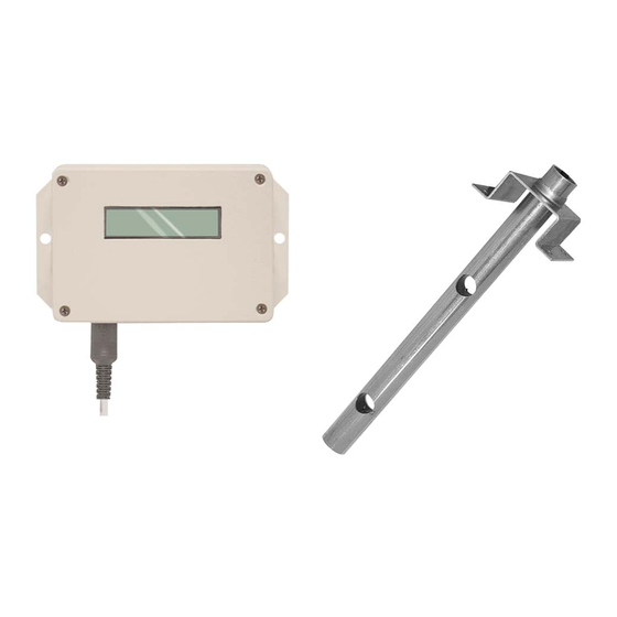
Single Probe/Single Analog Output Air Flow Measurement Device with Programmable Alarm
G G r r e e e e n n F F l l o o w w 1 1 0 0 0 0 0 0 S S e e r r i i e e s s
Greentrol Automation, Inc.
Installation, Operation and Maintenance Technical Manual
GF-1200-A
Advanced Outside Airflow Measurement Solution
Single Probe/Single Output Air Flow Measurement with
Programmable Alarm Options
Document Name: TM_GF-1200-A_R1D
Part Number: 960-0160
GreenTrol Automation, Inc. • •
156 Holly View Lane Loris, SC 29569 • • Toll Free: 877-4GN-TROL (877.446.8765) • • Internet: GreenTrol.com
Advertisement
Table of Contents

Related Manuals for Greentrol Automation GF-1200-A


Summary of Contents for Greentrol Automation GF-1200-A
- Page 1 Advanced Outside Airflow Measurement Solution Single Probe/Single Output Air Flow Measurement with Programmable Alarm Options Document Name: TM_GF-1200-A_R1D Part Number: 960-0160 GreenTrol Automation, Inc. • • 156 Holly View Lane Loris, SC 29569 • • Toll Free: 877-4GN-TROL (877.446.8765) • • Internet: GreenTrol.com...
- Page 2 1 through 24 . . .R1A ..Initial document release........09/26/2011 GreenTrol Automation, Inc. • •...
-
Page 3: Table Of Contents
GF-1200-A LCD Display Notifications and Features ........ - Page 4 Figure 5. GF-1200-A Transmitter Mechanical Detail Drawing ........
-
Page 5: Specifications
A simple to use Field Calibration Wizard permits one or two point field adjustment for installations that require field calibration or adjustment. The GF-1200-A transmitter provides a single analog output with selectable full scale ranges of 0-10VDC, 0-5VDC or 2-10VDC. -
Page 6: Gf-1200-A Features
‘Simple Equivalent Duct Diameter - ‘D’. To calculate Simple Equivalent Duct Diameter: ‘d’ = (duct width + duct height) GreenTrol Automation, Inc. • • 156 Holly View Lane Loris, SC 29569 • • Toll Free: 877-4GN-TROL (877.446.8765) • • Internet: GreenTrol.com... - Page 7 ™ GF-1200-A A IRFLOW EASUREMENT TATION Single Probe Air Flow Measurement and Programmable Alarm - Analog Output Automation, Inc. GF-1200-A DUCT PLACEMENT GUIDELINES Airflow Airflow Airflow Airflow Airflow Airflow C=3D C=1.5D C=0.75D C=1.5D C=0.75D 1.5D C=0.75D 0.75D 1.5D 0.75D B=4D 0.75D...
-
Page 8: Gf-1200-A Installation
Installation of the GF-1200-A consists first of installing the sensor probe, then installing the transmitter, and last, installing the power and analog signal wiring to the airflow station. The following paragraphs detail each of the individ- ual procedures required for installation of the GF-1200-A. Convenient check boxes are included to ensure that each step is completed. - Page 9 Figure 4 4 . G G F-1 1 200-A A S S ensor P P robe M M echanical D D etail GreenTrol Automation, Inc. • • 156 Holly View Lane Loris, SC 29569 • • Toll Free: 877-4GN-TROL (877.446.8765) • • Internet: GreenTrol.com...
-
Page 10: Gf-1200-A Transmitter Installation
GF-1 1 200-A A T T RANSMITTER I I NSTALLATION The GF-1200-A transmitter is designed for use in an environment between -20° F to 120° F (-28.8° C to 48.8° C) where it will not be exposed to rain or snow. In locations where precipitation may be encountered, a NEMA-4 enclosure must be provided to enclose the GF-1200-A transmitter. -
Page 11: Gf-1200-A Transmitter Wiring
Transmitter wiring consists of connecting the 24VAC input power, the analog output signal wires and optional alarm out- put wires at the GF-1200-A. Refer to Figures 6 and 7 for additional detail. Following installation, the airflow measure- ment station is ready for operation. Custom setup options (other than the default values) can be entered as outlined in the transmitter Setup Procedure. -
Page 12: Alarm Output Connections
Alarm O O utput C C onnections The GF-1200-A provides an alarm output that can be configured as relay dry contacts, or as direct drive (15 mA typical) for an external LED indicator. The alarm output type is set using the LED PWR jumper on the GF-1200-A circuit board as shown in Figure 6. - Page 13 TRANSFORMER OUTPUT, ALL GND CONNECTIONS MUST BE COMMON TO PREVENT DAMAGE, OR AN ISOLATION TRANSFORMER MAY BE USED. 3. ALL DEVICES ON MULTIPLE GF-1200-A TRANSMITTER INSTALLATIONS WITH A COMMON 24VAC SOURCE MUST BE WIRED IN-PHASE TO THE SAME TERMINALS (e.g.: PIN 6 to PIN 6, PIN 7 to PIN 7).
-
Page 14: Gf-1200-A Alarm Options And Description
Setup menu as an airflow alarm or system trouble alarm. The alarm output type, either exter- nal LED driver (15 mA typical), or relay dry contacts, is determined by the LED PWR jumper on the GF-1200-A transmit- ter circuit board (Figure 6). -
Page 15: Converting The Analog Output Volumetric Flow To Airflow Velocity
A test output signal between 0 and 100% of the selected full scale output (0-10 VDC, 0-5VDC or 2-10 VDC) can be pro- vided by the GF-1200-A to verify proper conversion of the output signals from the transmitter at the host control system. -
Page 16: Transmitter Initialization Mode
Changing t t he S S ystem o o f U U nits The GF-1200-A transmitter is shipped with the system of units set to US inch-pound units (IP), and will display units of measure as shown in the IP column of Table 2. To change to standard international (SI) units, simultaneously press and release the “UP”... -
Page 17: Gf-1200-A Lcd Display Notifications And Features
GF-1 1 200-A A A A larm O O ptions a a nd D D escription section of this manual. GreenTrol Automation, Inc. • • 156 Holly View Lane Loris, SC 29569 • • Toll Free: 877-4GN-TROL (877.446.8765) • • Internet: GreenTrol.com... -
Page 18: Factory Default Settings
Factory D D efault S S ettings The GF-1200-A transmitter is “plug and play” and does not require additional setup unless an optional feature is select- ed that requires configuration. Table 3 shows the factory default settings for the GF-1200-A. To change the Factory Default Settings, see: CHANGING FACTORY DEFAULT SETTINGS. -
Page 19: Transmitter Calibration
Setup M M enu O O ptions The GF-1200-A transmitter is configured at the factory to be fully operational when the sensor probes are connected and power is applied. Factory settings can easily be changed in the field through the Setup Menu, selected by simultaneous- ly pressing and releasing the “UP”... - Page 20 Figure 1 1 1. G G F-1 1 200-A A S S etup M M enu O O ption ( ( “IP S S YS”) GreenTrol Automation, Inc. • • 156 Holly View Lane Loris, SC 29569 • • Toll Free: 877-4GN-TROL (877.446.8765) • • Internet: GreenTrol.com...
- Page 21 {VEL} = Sensor velocity 1 = {VEL} 2 = {VEL} SENSOR TEMP ↑ {TEMP} = Sensor temperature 1= {TEMP} 2= {TEMP} GreenTrol Automation, Inc. • • 156 Holly View Lane Loris, SC 29569 • • Toll Free: 877-4GN-TROL (877.446.8765) • • Internet: GreenTrol.com...
-
Page 22: Field Adjustments
1200-A airflow station is installed. The inherent accuracy of the field reference measurement will not be better than ±5% of reading and measurement uncertainty can often exceed ±10%. Do not adjust the output of the GF-1200-A if the dif- ference between the transmitter and the field reference measurement is less than 10%. - Page 23 Figure 1 1 2. F F ield C C alibration W W izard M M enu ( ( all S S ystem o o f U U nits) GreenTrol Automation, Inc. • • 156 Holly View Lane Loris, SC 29569 • • Toll Free: 877-4GN-TROL (877.446.8765) • • Internet: GreenTrol.com...
-
Page 24: Troubleshooting
Greentrol Products are warranted for 12 months from shipment to the original equipment manufacturer only. Product will be repaired/replaced free of charge as described in the Terms and Conditions of Sale. GreenTrol Automation, Inc. • • 156 Holly View Lane Loris, SC 29569 • • Toll Free: 877-4GN-TROL (877.446.8765) • • Internet: GreenTrol.com...
Need help?
Do you have a question about the GF-1200-A and is the answer not in the manual?
Questions and answers