Table of Contents
Advertisement
Quick Links
USER'S MANUAL
Hi400i( D)
In order to apply this welding machine and use it safely, be sure to read and fully
understand this manual before use, inspection, or repair.
Headquarter : 16th floor, WeWork Building, 17- 37 Samsung- Dong,
Gagnam- Gu, Seoul, Korea
T EL : + 82- 2- 6230- 6041 FAX: + 82- 2- 598- 8467
Pohang 2nd plant: : 99 Yeongilmansandan- ro 88 Beon- Gil,
HeungHae- Eup, Buk- Gu, Pohang- Si, Gyeongsangbu- D0,
Korea
T EL: + 82- 54- 260- 0630
FAX: + 82- 54- 260- 0599
Advertisement
Table of Contents

Related Manuals for HYUNDAI WELDING Hi400i

Summary of Contents for HYUNDAI WELDING Hi400i
- Page 1 USER'S MANUAL Hi400i( D) In order to apply this welding machine and use it safely, be sure to read and fully understand this manual before use, inspection, or repair. Headquarter : 16th floor, WeWork Building, 17- 37 Samsung- Dong, Gagnam- Gu, Seoul, Korea T EL : + 82- 2- 6230- 6041 FAX: + 82- 2- 598- 8467 Pohang 2nd plant: : ...
-
Page 2: Table Of Contents
3. Setting of Robot Parameters ( Set Current, Voltage) 6. Product Maintenance Schematic Diagram – Hi400i 220V I /0 I nterface Schematic Diagram – Hi400i 220V Serial I nterface 3. Hi- COMM I O I nterface ( PCB6) Detailed Schematic Diagram 4. -
Page 3: Safety Precautions
1. Safety Precautions ▶ Before using the welding machine, be sure to read and understand 'Safety Precaution'. ▶ Please keep the Safety Precaution when you use the welding machine since it states important issues regarding the safety for users. ▶ I n this manual, the degree of risk is classified into the following three classes for situations that may occur due to the inappropriate usage. - Page 4 1. Safety Precautions HAZARD Electric shock may result in death. • Contact with welding parts may cause fatal shock or serious burns. • Be careful because the wire and the work piece are welded when the output of the welding machine is generated. •...
- Page 5 1. Safety Precautions HAZARD Welding may cause fire and explosion. • Spatter during welding may cause fire or explosion. • Hot work piece immediately after welding can cause fire or burns. • Welding on airtight containers such as pipes, drums and tanks can cause an explosion.
- Page 6 1. Safety Precautions WARNI NG Electromagnetic fields can harm the operator's body. • Electromagnetic fields may affect pacemakers. 1) T he worker should work away from the magnetic field. 2) T he cardiac pacemaker wearer should not be close to the welding power source and the welding area.
- Page 7 1. Safety Precautions CAUT I ON Arc light can cause serious burns to your eyes and skin. 1) I n the arc light generated during welding, ultraviolet rays and I nfrared rays are generated, which damages the eyes and skin. 2) When you see welding work or welding, protect your eyes and face by wearing welding faces, safety glasses, and welding helmets with adequate shielding ability.
- Page 8 1. Safety Precautions CAUT I ON Noise can cause hearing impairment. 1) Noise from some work and equipment can damage your hearing. 2) I f the noise level is high, wear an approved ear protector. T o ensure user's safety, improper use of the product is CAUT I ON prohibited.
-
Page 9: Operating Precautions
2. Operating Precautions For safe and correct use of the product, please read and understand the information below before using the welding machine. ▶ Place of I nstallation 1) I nstall the welding machine in a flat place without any dust or moist. 2) I nstall the welding machine in a place with adequate airflow, not in an enclosed space. - Page 10 2. Operating Precautions ▶ Product Movement T he welding machine is equipped with two eye- bolts for movement. User may bump into a moving welding machine or CAUT I ON the welding machine may fall and cause injury. • When moving or transporting, be sure to secure the welding machine on the transport device and move.
- Page 11 2. Operating Precautions ▶ Duty Cycle and Overheat T he duty cycle of welding machine is a percentage of the operating cycle of welding machine that can operate at a given to rated power. T he cycle is calculated based on 10 minutes. For example, if the duty cycle of a 400A welding machine is 60%, it can be used at the rated maximum output ( 400A , 34V ) for 6 minutes welding in a 10- minute cycle and a 4 minute break.
-
Page 12: Product Configuration
▶ Standard Configuration of the product Followings are the composition of this welding machine. Basic Components I tem Specification Quantity Welding power source Hi400i Wire feeder RF- Hi400 I nterface converter Hi- COM M Accessory Components I tem Standard Specification... -
Page 13: Product Rating And Installation
4. Product Rating and Installation ▶ Welding power source rated specification Model Hi400i 18.6kV A Rated input 3P, 220V / 380V / 440V Rated input voltage, phase 50/60Hz Rated frequency 400A Rated output current 34V DC Rated load voltage 30A ~ 400A... - Page 14 2) Be sure to insulate the conductive part where the bare wire is exposed using an insulating material. ▶ Robot T ype Wiring Item Specification Welding power source Hi400i Wire feeder RF- Hi400 Wire feeder mount bracket Depend on user's robot specifications T orch...
- Page 15 4. Product Rating and Installation ▶ Input Power Connection Electric shock may result in death. HAZARD Welding may cause fire and explosion. • Ensure that electrical qualified personnel works on input power connections and voltage changes. • T urn off the circuit breaker for input power before working. •...
- Page 16 4. Product Rating and Installation ▶ Output Cable Selection WARNI NG Electric shock may result in death. • Use a cable sized for the rated power of the welding machine. • Please select and install the cable according to the information below. 1) Use cables as short as possible.
- Page 17 4. Product Rating and Installation ▶ Output Cable Selection T able Rated Output Current( A) Minimum Cross Section ( mm²) 60% Duty Cycle 100% Duty Cycle 10 or more 10 - 16 16 - 25 25 - 36 35 - 50 50 - 70 * T he above table shows the cable size compared to the output current according to I EC 60974- 12.
-
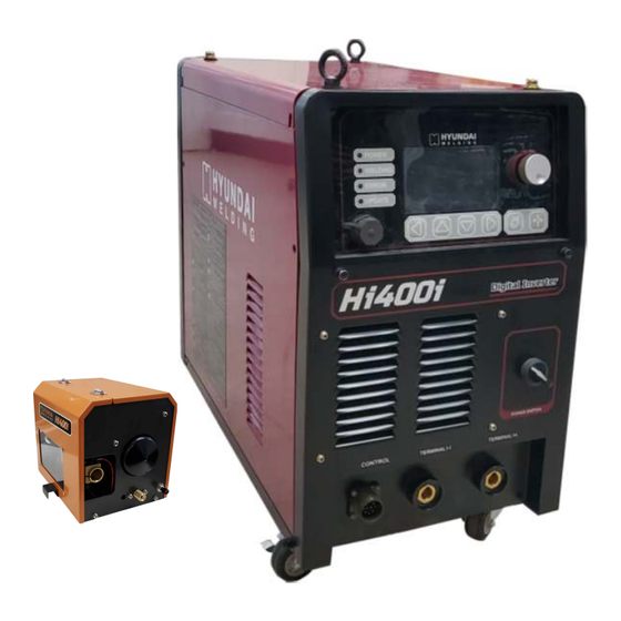
Page 18: Operation And Function Of Product
Operation and Function of Product ▶ Welding Power Source [1] HM I : A djust/display the control values/status of the welding machine. [2] Power switch : T urns ON/OFF the power of the welding machine. [3] Output terminal ( + ) : Wiring the output cable ( to wire feeder) . [4] Output terminal ( - ) : Wiring the earth cable ( to work piece) . - Page 19 Operation and Function of Product ▶ Welding Machine Rear Panel [1] M S connector1 : Connect Hi- COM M 1. [2] M S connector2 : Connect Hi- COM M 2. [3] I nput terminal : Connect 3- phase power input cable. [4] Circuit protector : T urn on/off the switch to supply main power to the welding machine and protect the circuit.
-
Page 20: Configuration And Function Of Display Panel
Operation and Function of Product Configuration and Function of Display Panel <Hi400i Display Panel> <Hi400iD Display Panel> - 19 - VER 1.0... - Page 21 <Hi400iD HMI Pendant> [1] HM I : Display set / output / status values. [2] A djustment/I nput K NOB : can change the set value / parameter by rotating the K NOB. I t can enter or return ( or save) into the setting value/parameter switching mode by adjusting the K NOB.
-
Page 22: Screen Configuration Function And Method To Set
Operation and Function of Product 2. Screen Configuration Function and Method to Set 1) System Booting Screen [1] : T he system booting starts when welding power source allows to turn on. When the booting starts, the progress bar that displays booting status increases. A s progress bar is fully filled, booting is completed and basic setting screen is displayed. - Page 23 Operation and Function of Product [5] : Display the ratio of set synergic voltage. Command voltage setting method can be set when synergic is selected. [6] : Display the setting ( standby) / output ( on welding) feeding speed. When adjusting [3] the welding current after its selection, the setting value of feeding speed by the pre- programmed welding database is displayed.
- Page 24 Operation and Function of Product Parameter [ Unit] Initial value Parameter [ Unit] I nitial value Database setting value Welding current Welding voltage in accordance with [ A] [ V] welding current Database setting value Feeding speed in accordance with Synergic [ m/min] welding current...
- Page 25 Operation and Function of Product * Explanation of adjustable parameter and setting value in the Job setting screen are shown in the table at below. Parameter [ Unit] Setting Value 1) LSM mode : Low spatter welding mode * Example of welding wave 2) DCM mode : General DC welding mode Welding mode * Example of welding wave...
- Page 26 Operation and Function of Product 5) Welding Start Parameters Setting Screen [22] : Set the wire slow down feeding speed. [23] : Set the shielding gas pre- flow time. [24] : Set the HOT ST A RT current. [25] : Set the HOT ST A RT time. [26] : Set the HOT ST A RT ending detection level.
- Page 27 Operation and Function of Product Operation and Function of Product 6) Welding Crater Parameters Setting Screen [27] : Set the crater welding current. Display the crater welding current by pre- programmed welding database when selecting and adjusting the crater feeding speed[29]. [28] : Set the crater welding voltage.
- Page 28 Operation and Function of Product * 2- Step ① Pre- flow time, ② No load output period, ③ Start welding period, ④ M ain welding period, ⑤ Crater welding period, ⑥ End welding period, ⑦ Post- flow time * 4- Step ①...
- Page 29 Operation and Function of Product * T he parameters and adjustment ranges that can be adjusted within the crater parameters setting screen are shown in the table below. Parameter [ Unit] Min. Max. Adjustment Unit Crater welding current [ A] Crater welding voltage[ V] 10.0 36.0...
- Page 30 Operation and Function of Product * I nformation on the setting value of the adjustable parameter within the welding end parameters setting screen are shown in the table at below. Parameter [ Unit] I nitial Min. Max. Adjustment Unit Burn- Back output [ %] Burn- Back output [ ms] 1,023 Anti- Stick output voltage [ DAC]...
- Page 31 Operation and Function of Product [37] : Users authority of welding power source can be changed. A ccording to users' authority, setting parameters screen of internal control parameters can be activated or non- activated. Changes in accordance with users' authority are as follows. Users Authority Initial Setting Displayed Items...
- Page 32 Operation and Function of Product T he information on the setting values of the adjustable parameters within the welding system setting screen is shown in the table below. Adjustment Name Initial Min. Max. Unit Unit HM I , Hi- COM M 1, Hi- COM M 2, Wire Feeder A, V, m/min setting unit HM I , Hi- COM M 1, Hi- COM M 2, Wire Feeder System parameters setting unit...
- Page 33 Operation and Function of Product 9) System Status / I nformation Parameters Display Screen [47] : Display accumulated operation time of DC LI NK relay of power converter. [Hour : M in : Sec] [48] : Display accumulated operation time of cooling fan.
- Page 34 Operation and Function of Product [56] : Display accumulated operation number of solenoid valve. When it turns OFF- > ON, the number is accumulated. [57] : Display accumulated operation number of stick check ( Detection between wire and work piece) . When stick check is on, the number is accumulated. [58] : Display accumulated occurred number of welding output load.
-
Page 35: Setting Of Robot Parameters ( Set Current, Voltage)
Operation and Function of Product When there is an error during the operation of welding machine, a error indicator lamp( Red) of HM I lights on and a beep sound comes to indicate that an error has occurred. A t this time, the user use the screen to move into the error log screen to check the error code, the error indicator lamp and the beep sound turn off. -
Page 36: Product Maintenance
Product Maintenance 1. Schematic Diagram - Hi400i 220V I /O Interface - 35 - VER 1.0... -
Page 37: Schematic Diagram - Hi400I 220V I /0 I Nterface
Product Maintenance 1. Schematic Diagram - Hi400i 220V I/O I nterface - 36 - VER 1.0... -
Page 38: Schematic Diagram - Hi400I 220V Serial Interface
Product Maintenance 2. Schematic Diagram - Hi400i 220V Serial Interface - 37 - VER 1.0... - Page 39 Product Maintenance 2. Schematic Diagram - Hi400i 220V Serial Interface - 38 - VER 1.0...
-
Page 40: Hi- Comm I O I Nterface ( Pcb6) Detailed Schematic Diagram
Product Maintenance 3. Hi- COMM I O Interface ( PCB6) Detailed Schematic Diagram D- SUB 25PI N FEMALE ( 25pin) PIN name Explanation ROBOT _GND + 24V DC power GND connected to the robot controller M A I N_WELD_SET _A A nalog input signal for main welding voltage command CRA T ER_WELD_SET _A A nalog input signal for crater welding voltage command... -
Page 41: Hi- Comm Serial I Nterface ( Pcb6) Detailed Schematic Diagram
Product Maintenance 4. Hi- COMM Serial Interface( PCB6) Detailed Schematic Diagram D- SUB 15PIN FEMALE ( 15pin) PIN # PIN name Explanation ROBOT _GND + 24V DC power GND connected to the robot controller ROBOT _CA N_L CA N communication signal connected to the robot controller ROBOT _RS232_T X RS- 232 communication signal connected to the robot controller ROBOT _RS485_L... -
Page 42: Hi400Id Devicenet Interface( Mc2, Mc3) Detailed Schematic Diagram
Product Maintenance 5. Hi400iD DeviceNet Interface( MC2, MC3) Detailed Schematic Diagram 핀번 핀명 설명 + 24V DC power GND connected to the robot controller + 24V DC connected to the robot controller CA N communication signal connected to the robot CA N L controller CA N communication signal connected to the robot... -
Page 43: Parts List - Hi400I Welding Power Source
Product Maintenance Product Maintenance 6. Parts List - Hi400i Welding Power Source - 42 - VER 1.0... - Page 44 Product Maintenance Signal Part name Part number Specification Note Capacitor 45000423 10uF/630V Capacitor 45000439 103/1kV C2,3 Protector 45000206 DCP73BH 73A 380V 45000424 CT 800T CT 1 45000421 T M 2A 300- 04DA 15 CT 2 Diode 40006421 M DS100A 1600V Diode 40005610 EST 100BN40S...
-
Page 45: Periodic Maintenance Of Parts According To Usage T Ime/Frequency
DC LI NK relay exceeds 100,000, recommend to replace PCB2. When accumulated number of stick check exceeds 2,700,000, recommend to replace RL2 of PCB1. When ON/OFF accumulated occurred number of welding output exceeds 2,700,000, recommend to replace RL3 of PCB1. Outline Drawing- Hi400i - 44 - VER 1.0... -
Page 46: Wire Feeder
7. Wire Feeder 1. Specification Model RF- Hi400 Communication ( CA N) Control method DC24V / Encoder Control Motor spec. and control 4Roll 4Geared Drive type 0.8~20 m/min Feeding speed 0.9, 1.0, 1.2mm Wire diameter A sia Spec. T orch connection 192 * 242 * 197( mm) Dimension ( W* D* H) 6.1( K g) -
Page 47: Parts List - Rf- Hi400 Wire Feeder
7. Wire Feeder 3. Parts List – RF- Hi400 Wire Feeder Signal Part Name Part No. Specification Note M 8 (Torch connector), T ORCH Torch adaptor 45000441 M 8 (Output cable) CONNECT I ON 9/16 UNF Gas nipple 45000448 NIPPLE ø8 4p Push pull connector Circular connector SHOCK SENSOR... -
Page 48: Periodic Maintenance Of Parts According To Usage T Ime/Frequency
7. Wire Feeder Periodic Maintenance of parts according to Usage T ime/Frequency When accumulated operation time of the feeding motor exceeds 4,000 hours, check the condition of wire feeder roller, of the DRI V E ROLLER, and replace it if noise or friction occurs. When accumulated operation time of the feeding motor exceeds 2,000 hours, check the wear on wire feeder roller by naked eyes and replace it if the wear condition is excessive. -
Page 49: Outline Drawing - Rf- Hi400
7. Wire Feeder Outline Drawing – RF- Hi400 - 48 - VER 1.0... -
Page 50: Troubleshooting And Inspection
8. Troubleshooting and Inspection Regular Maintenance HAZARD Electric shock may result in death. • Before and after connecting the power source be sure to check the power source status during welding and voltage with a tester before working. 1) Be sure to work by a qualified electrician. 2) For installation and maintenance inspection, be sure to cut off the power source at the input of the distribution switch board circuit protector before working for at least 5 minutes. -
Page 51: Check In Accordance With The Error Code
8. Troubleshooting and Inspection Check in accordance with the Error Code Error Code Cause Countermeasure 3- Phase under input voltage 1. Check 3- Phase input voltage. detection ( - 15% or less) - Within ±15% of rated input voltage 2. Replace PCB1. 3- Phase over input voltage 3. - Page 52 8. Troubleshooting and Inspection 1. Check if wire remains. 2. check the condition of work piece such as burn through. 3. Check an abnormality in the feeding of No output current detected for more wire. than 2 seconds during welding - Check the operation of wire feeder.
- Page 53 8. Troubleshooting and Inspection 1. Check 3- phase input voltage. PCB3 power over voltage detection - Within ±15% of rated input voltage - 28.8V dc or more 2. Replace V S1 if it is more than the reference - 21( + ) - GM( - ) measured voltage voltage of the measured voltage.
- Page 54 8. Troubleshooting and Inspection 1. Check that the welding start time is within 10 seconds after the welding torch signal. 2. Check if wire remains. No load output continuous ( more 3. Check an abnormality in the feeding of wire. than seconds) error...
- Page 55 8. Troubleshooting and Inspection 1. I nitialize welding machine ( Refer Welding control PCB NV SRA M no 5- 2- 2 of this manuel) response error 2. Replace PCB1. 3. Please contact our service team. I nternal CA N communication error 1.
- Page 56 8. Troubleshooting and Inspection 1. Check the shock sensor alarm status. 2. Check the operation sensor of shock sensor within robot motion range. - T orch length ( short) or shock sensor alarm Wire feeder shock sensor error during robot movement 3.
-
Page 57: Product Firmware Update
8. Troubleshooting and Inspection 3. Product Firmware Update T o update the welding machine's firmware, the welding power- integrated firmware file ( Hi400i_V er_*.*.*.hwf) and USB flash memory are required. A fter connecting the USB flash memory to the USB port of the PC, format ( FA T 32) as follows. I f you insert the USB flash memory with the firmware stored in the USB port of the welding power source front panel, alarm UPDA T E LED status in front after 10 seconds and the firmware update will proceed automatically. - Page 58 8. Troubleshooting and Inspection When the welding power source internal PCB firmware update is completed, all status LED are lighted on. When the status of LED stays on for more than 3 seconds, the USB flash memory is automatically rebooted and the firmware update is completed. - 57 - VER 1.0...
Need help?
Do you have a question about the Hi400i and is the answer not in the manual?
Questions and answers