Table of Contents
Advertisement
Quick Links
Advertisement
Table of Contents

Related Manuals for Merlin 300


Summary of Contents for Merlin 300
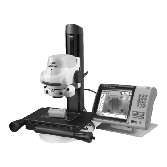
- Page 1 User Guide Merlin 300 2-axis Video Measuring System...
- Page 3 Merlin is an easy to use compact system, that can be combined with a range of accessories including alternative magnification, footswitch, image capture and data processing options. For further details, contact your Vision Engineering representative or distributor.
-
Page 5: Table Of Contents
Stage Glass Levelling PRODUCT FAMILY ACCESSORIES & ADDITIONAL FEATURES OPERATION & SETUP Main system controls HOW TO USE YOUR MERLIN MEASURING SYSTEM GETTING THE MOST FROM YOUR MERLIN ROUTINE MAINTENANCE Substage lamp changing OTHER SOLUTIONS FROM VISION ENGINEERING Stereo inspection systems Non-contact measuring systems SERVICE &... -
Page 7: Packing Contents
PACKING CONTENTS Head PACKING CONTENTS Camera Focus assembly Objective LED surface illuminator Stage & Stand Column & Stand Stage Stage Glass www.visioneng.com/support Merlin 300 2-axis Video Measuring System... -
Page 8: Microprocessor
PACKING CONTENTS Microprocessor Quadra-check 300 microprocessor Microprocessor stand Accessories Objective lenses Footswitch (optional) Merlin 300 2-axis Video Measuring System www.visioneng.com/support... -
Page 9: Assembly
NOTE: Ensure the stage glass is in contact with all 4 supports. www.visioneng.com/support Merlin 300 2-axis Video Measuring System... -
Page 10: Head Attachment
Position the head assembly as required and secure it. Objective lens attachment Place the objective lens (with integral iris control ) into position secure it with a half turn to the right For further information, see Objective lens on page 10. Merlin 300 2-axis Video Measuring System www.visioneng.com/support... -
Page 11: Led Surface Illuminator
(looking from the front) and the spacer and locking washer are correctly positioned on the right-hand fixing. Note: Do NOT overtighten either fixing bolt. www.visioneng.com/support Merlin 300 2-axis Video Measuring System... -
Page 12: Cable Connection
Getting started Switch on Merlin. Switch on QC-300 and follow on screen instructions for crossing reference marks. The System is now ready for use. Stage Glass Levelling Use the X axis and Y axis... -
Page 13: Product Family
Objective Lenses x1 MN-007 x2 MN-008 x5 MN-009 LED Substage LED Surface Illuminator Illuminator MN-006 MN-004 QC-300 2-axis Precision Measuring Stage Microprocessor 100mm x 150mm (6"x4") MN-005 MN-003 Dust Cover MN-103 Footswitch MN-016 www.visioneng.com/support Merlin 300 2-axis Video Measuring System... -
Page 14: Accessories & Additional Features
ACCESSORIES & ADDITIONAL FEATURES ACCESSORIES & ADDITIONAL FEATURES A wide range of optional accessories can be used with the Merlin measuring system, further expanding on system capability. For more information, please contact your Vision Engineering branch, local authorised distributor or visit our website. -
Page 15: Operation & Setup Main System Controls
OPERATION & SETUP Main system controls OPERATION & SETUP Locking Lever (Height Adjustment Control) Focus Control Travel Stop Y Axis Control Surface Illumination Thumbwheel Substage Illumination Thumbwheel X Axis Control Stabilising Foot www.visioneng.com/support Merlin 300 2-axis Video Measuring System... -
Page 16: How To Use Your Merlin Measuring System
Move the travel stop up to the base of the focus assembly and lock it in place. To achieve the optimum results from your Merlin measuring system, the illumination and optics need to be optimised to provide the best possible image. Certain lighting configurations are better for some applications than others. - Page 17 A cir cle is mea sured by prob ing a min i mum of 3 points Fur ther de tails on tak ing mea sure ments can be found in the QC-300 mi cro pro ces sor user guide. Good Working Practices When taking points on features the point should always be approached in the same fashion e.g.
-
Page 18: Getting The Most From Your Merlin
GETTING THE MOST FROM YOUR MERLIN To achieve the very best from your Merlin non-contact measuring system, you should carry out regular, routine maintenance as well as undertaking a schedule of servicing and calibration (see service & calibration record page) Routine Maintenance (see page 13) •... -
Page 19: Routine Maintenance
Illuminator base plate and remove it, complete with Substage Illuminator unit Disconnect two flying wires from the internal wires and remove the substage illuminator unit. Fit the new unit by reversing the above procedure. www.visioneng.com/support Merlin 300 2-axis Video Measuring System... -
Page 20: Other Solutions From Vision Engineering
Available in boom and rigid • 77mm – 1.75mm field of stand configuration with a wide range Lynx view of optional accessories (e.g. lighting, • Cam era op tion cameras) • Eyepieceless view ing sys tem Merlin 300 2-axis Video Measuring System www.visioneng.com/support... -
Page 21: Non-Contact Measuring Systems
PC based Video Edge Detection. 2 and automatic • Motor ised stage move ment 3 axis motorised stage movement • 2 or 3 axis ca pa bil ity controlled by QC-5000 PC software. www.visioneng.com/support Merlin 300 2-axis Video Measuring System... -
Page 23: Service & Calibration Record
SERVICE & CALIBRATION RECORD SERVICE & CALIBRATION RECORD Merlin Serial Number ________________ Stage Serial Number ________________ Service Type Comments Date of Service Date of Next Service Company Signature... -
Page 25: Warranty
WARRANTY WARRANTY This product is warranted to be free from defects in material and workmanship for a period of one year from the date of invoice to the original purchaser. If during the warranty period the product is found to be defective, it will be repaired or replaced at facilities of Vision Engineering or elsewhere, all at the option of Vision Engineering. - Page 26 For more information... Vision Engineering has a network of offices and technical distributors around the world. For more information, please contact your Vision Engineering branch, local authorised distributor, or visit our website. Vision Engineering Ltd. Vision Engineering Inc. Vision Engineering Ltd. Vision Engineering Ltd.
Need help?
Do you have a question about the 300 and is the answer not in the manual?
Questions and answers