Table of Contents
Advertisement
Quick Links
Advertisement
Table of Contents

Related Manuals for Spectra LR50


Summary of Contents for Spectra LR50
- Page 1 LR50 Laser Receiver User Guide •...
- Page 2 Introduction ® Thank you for choosing the Spectra Precision Laser Receiver LR50. The laser receiver is a rugged, multi-purpose, electronic sensor that detects laser light generated by rotating laser transmitters. The receiver works with nearly all models of rotating lasers and detects both visible and invisible beams.
-
Page 3: Maintenance And Care
Safety Please follow all operating and safety instructions in this guide and that of your machinery. Perform periodic checks of the product’s performance. Trimble or its representatives assume no responsibility for results of the use of this product including any direct, indirect, consequential damage, and loss of profits. Check your work frequently. -
Page 4: Features And Functions
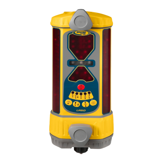
Features and Functions 1. Aluminum-Cast Upper and Lower Housings—protect the receiver. 2. Polycarbonate Housing—protects the electronics. 3. Receiving Windows—include four sets of photocells that are equally spaced to allow for 360 degree reception. 4. Super-Bright LEDs—are highly visible and graphically display blade or bucket position. 5. -
Page 5: Controls And Displays
Controls and Displays 5-Light Blade-Tilt Indication On-Grade Low Battery Deadband Location Indicators Indicator (Accuracy) Combination Indicators Standard Center Offset Wide Fine Deadband On-Grade, On-Grade, Deadband Deadband Grading Excavating, Plumb On Touchpanel Buttons Secondary Function Blade-Tilt Plumb Accuracy Laser-Beam Laser Accuracy Indication Averaging Out-of-Level... -
Page 6: Alkaline Batteries
Installing and Recharging the Batterines Alkaline Batteries 1. Hold the receiver so the accessory connector is pointing up. 2. Remove the dust cap from the accessory connector. 3. Loosen the two thumb screws and remove the battery-access cover. 4. Install four “C” cell alkaline batteries as shown on the label diagram inside the battery compartment noting the (+) and (–) terminals. -
Page 7: Battery Safety
Battery Safety Built-in overcharging protection prevents damage to the receiver if it is left on charge after being fully charged. Charge protection also prevents damage if you accidentally try to recharge alkaline batteries. CAUTION: Do not attempt to charge alkaline or other disposable batteries. Note: The batteries should only be charged when the receiver is between 0 °C to 45 °C (32 °F to 113 °F). -
Page 8: Using The Receiver
Using the Receiver Operation Power Button 1. Press the power button to turn on the receiver. Notes: All the LEDs light briefly. Quickly following, each LED grade-display row turns on and off from top to bottom and each status indicator turns on and off. - Page 9 Blade-Tilt Button Press the blade-tilt button to turn on/off the display. The LED status indicators display in a rolling sequence. When the function is turned on, the LEDs sequence from the center outward. When the function is turned off, the LEDs sequence from the outer LEDs inward.
- Page 10 Offset on-grade is selected for typical excavation operations. This mode gives more information and a larger display area above on-grade. This mode also enables the plumb indication, which shows when the mast and receiver are perpendicular to the ground (plumb), for more accurate grade readings. Each selection uses a different array of LEDs.
- Page 11 Deadband (Accuracy) Button Each on-grade location has three deadband or accuracy selections: fine, standard, and wide. The center or grading deadbands are smaller than the offset or excavating deadbands. To show the current selection, press the button once; the status LED flashes. To change the current selection, press the button again.
- Page 12 Display-Brightness Button The display-brightness button controls the brightness for the LED grade display and blade-tilt display. Options include Bright and Dim. Use dim for normal and lower light conditions and bright for sunny daytime operation. Dim conserves battery life. When the receiver is out of the laser beam and the display-brightness button is pressed, the LEDs display a circle showing the current setting.
- Page 13 Out-of-Beam Indication The receiver has an out-of-beam (OOB) function. When it is turned on, the LED grade display indicates that the receiver has moved beyond the vertical laser-reception range. A sequence of LEDs indicates which direction to move the blade or cutting edge to pick up the laser beam.
-
Page 14: Installation
Installation General WARNING: Follow all safety precautions as discussed in the machine’s user guide. Also follow all excavation and safety requirements and practices. 1. Set up the laser in an appropriate location for receiver visibility and efficient machine operation. For more information about laser setup, please refer to the laser’s user guide. - Page 15 Make sure dozer mast is vertically aligned with the blade (both front-to-back and side- to-side) when the blade is in its normal operating position. For excavation, the mast typically points towards the bucket teeth. For additional installation details, see “Slope Matching.” Typical dozer Typical excavator installation...
- Page 16 2. Set up the laser in an appropriate location for receiver visibility and efficient machine operation. Turn on the laser. 3. Turn on the receiver, select center on-grade (grading mode), and select the smallest deadband. 4. To mount the receiver on the mast, turn the top and bottom mounting knobs counterclockwise until the clamps in back open enough to fit around the mounting mast.
- Page 17 Slope Matching The blade-tilt indicator can be nulled or set to zero for a blade slope other than level. This function is used for matching an existing slope or setting the blade to a predetermined slope. The factory default setting for the blade-tilt indicator is level. To change the blade-tilt indicator at a slope other than level: 1.
- Page 18 Excavating When an excavator or backhoe is being used, the dipper arm should be vertical or near vertical and the bucket positioned so that it can easily be put in the same position each time a grade reading is taken. The bucket can be fully extended or curled as long as the position is consistent when grade readings are taken.
- Page 19 7. Mount the receiver on the mast, and adjust the dipper arm so that the receiver is within the plumb range—LEDs solid. Adjust the plumb-accuracy indication if desired. 8. Slide the receiver up or down until you get a solid on-grade display. 9.
- Page 20 3. Determine the distance from the laser to the bottom of the trench (L). This is the setup length. The length is the height of the instrument (HI) plus the depth of cut from the benchmark to the bottom of the trench (C). 4.
- Page 21 Notice to Our European Union Customers For product recycling instructions and more information, please go to: www.trimble.com/environment/summary.html Recycling in Europe To recycle Trimble WEEE, call: +31 497 53 2430, and ask for the “WEEE associate,” or mail a request for recycling instructions to: Trimble Europe BV c/o Menlo Worldwide Logistics Meerheide 45...
-
Page 22: Specifications
Specifications Beam Reception Range 360 degrees Operating Range Over 460 m (1500 ft) radius, laser dependent Laser RPM Minimum: 105; Maximum: 1200 Vertical Reception 171 mm (6.75 in.) Accuracy: Fine Standard Wide Center On-Grade 5 mm 10 mm 20 mm (Grading) (0.20 in.) (0.40 in.) -
Page 23: Declaration Of Conformity
Declaration of Conformity We herewith declare, in exclusive responsibility, that the receiver was developed, designed, and manufactured to conform to the Council Directive 89/336/EEC (Electromagnetic Compatibility) including their amendments up to the date mentioned below. Equipment Type / Environment: Measurement, Control, and Laboratory Equipment The following harmonized standards were applied: EN61326: 1997 +A1: 1998 + A2: 2001 Electromagnetic compatibility (EMC) -
Page 24: Warranty
Warranty Trimble warrants the receiver to be free of defects in material and workmanship for a period of two years. Trimble or its authorized service center will repair or replace, at its option, any defective part for which notice has been given during the warranty period. If required, travel and per diem expenses to and from the place where repairs are made will be charged to the customer at the prevailing rates.
Need help?
Do you have a question about the LR50 and is the answer not in the manual?
Questions and answers