Table of Contents
Advertisement
Quick Links
Advertisement
Table of Contents

Subscribe to Our Youtube Channel
Related Manuals for Spectra SP80


Summary of Contents for Spectra SP80
- Page 1 SP80 GNSS Receiver User Guide...
- Page 2 Canadian Department of Communications. SP80 User Guide, Rev. A, December 2013. Le présent appareil numérique n’émet pas de bruits radioélectriques dépassant les limites Limited Warranty Terms and Conditions applicables aux appareils numériques de Classe B...
- Page 3 These two devices receiver’s velocity is computed to be greater than are part of the SP80 standard accessories list. 1000 knots, or its altitude is computed to be above CHARGE THE BATTERIES ONLY IN THE 17,000 meters (59,055 feet).
- Page 4 Other coun- tries require end-user licensing. For licensing infor- mation, consult your local Spectra Precision dealer. Before operating the receiver with the UHF kit, deter- mine if authorization or a license to operate the UHF kit is required in your country.
-
Page 5: Table Of Contents
Left-Side View...............8 Phase Center Location ............8 Height Mark ................9 Special Key Combinations ............10 Screen Illumination & Buzzer..........10 Using SP80 for the First Time ............11 Charging the Batteries............11 Inserting the Batteries............12 Inserting Cards ..............13 Setting up the Receiver ............14 Running a Survey ..............14 Ending the Survey ...............15... - Page 6 Base Setup..................29 Network Base ..............29 Base in CSD Mode ...............29 Base With Radio ..............29 Internal vs. External Power Source.........30 Recording/Downloading GNSS Raw Data ..........31 Data Recording Flowchart.............31 Step-by-Step Procedure............31 Downloading Raw Data Files ..........34 Charging Batteries - Using External Power ......... 35 Batteries Vs.
-
Page 7: About Spectra Precision Sp80
240-channel “6G” chipset, the SP80 system is optimized for tracking and processing signals from all GNSS constellations. In addition, SP80 is the most connected GNSS receiver in the industry. It is the first to offer a unique combination of integrated 3.5G cellular, WiFi and UHF communications with SMS, email and anti-theft features. -
Page 8: Sp80 Packout
(Not Applicable) Theft Technology Adhesive Sticker. (1) When applicable, the items part of the standard packout may be ordered separately as spare parts, using the P/Ns specified in this column. NOTE: The SP80 User Guide may be downloaded from: www.spectraprecision.com/products/gnss-surveying/SP80/... -
Page 9: Optional Accessories
RS232-to-USB adapter cable 90938-SPN (1) When applicable, the items part of these three SP80-specific kits may be ordered separately as spare parts, using the P/Ns specified in this column. (2) DOES NOT include the UHF antenna. See other optional accessories... -
Page 10: Other Optional Accessories
Other Optional Accessories Item Ordering P/N: Picture UHF whip antenna, Procom, half-wave, with TNC adapter: • 410-430 MHz C3310190 • 430-450 MHz C3310196 • 450-470 MHz C3310188 UHF whip antenna, ¼ wave, with TNC adapter: • 410-430 MHz 67410-12 • 430-470 MHz 67410-11 Coaxial adapter cable (for use with P/N 95672) 96845 ADL Vantage Pro Accessories Kit. -
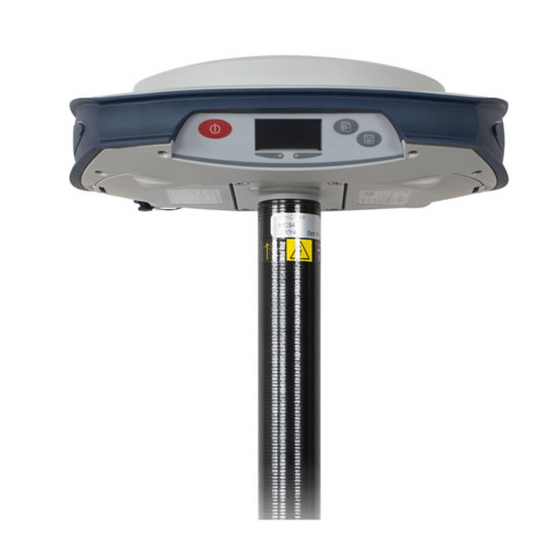
Page 11: Discover Your New Equipment
Discover Your New Equipment Take a few minutes to discover your new SP80. Front Panel [1] [2] [3] [5] • [1]: Power button. Hold the button depressed for about two seconds to turn on or off the receiver. • [2]: Display screen •... -
Page 12: Bottom View
Bottom View [10] [11] [12] • [7]: Front panel (see details above) • [8]: Battery A compartment trapdoor • [9]: Battery B compartment trapdoor CAUTION - THE TWO TRAPDOORS SHOULD BE OPENED ONLY FOR INSERTING OR REMOVING BATTERIES. THE REST OF THE TIME, PLEASE ALWAYS KEEP THEM FULLY CLOSE TO PRESERVE WATERTIGHTNESS. -
Page 13: Right-Side View
Right-Side View [13] [14] [15] • [13]: SD card holder. An SD Card is a removable memory extension that can be used to: – Record GNSS raw data – Copy G-files from the internal memory – Or install firmware upgrades Maximum capacity according to SDHC standard: 32 GB The SD Card should be inserted into the receiver with its label side oriented downward (pins upward). -
Page 14: Left-Side View
Left-Side View [17] [16] • [16]: Rubber flap protecting the USB connector. To preserve watertightness, ALWAYS KEEP FULLY CLOSE when you don’t need to use the USB port. • [17]: USB connector emulating standard RS232 serial port (port B). For use in troubleshooting only. Phase Center See diagram below. -
Page 15: Height Mark
Height Mark The height mark ([18]) is nested on the shock absorber diagonally to the front panel. [18] When the receiver is mounted on a tripod – for use as a base for example – making a slant measurement to determine the instrument height is often more convenient than making a vertical measurement from the ground mark to the antenna base. -
Page 16: Special Key Combinations
Special Key The SP80 has three different key combinations requiring that the receiver be initially turned off. See table below for details. Combinations Key combination Function Starts a firmware upgrade sequence from the file stored in the SD Card. (Power + Scroll buttons) -
Page 17: Using Sp80 For The First Time
Using SP80 for the First Time WARNING - This receiver uses one or two rechargeable Lithium-ion batteries. To avoid personal injury or equipment damage, make sure that you read and understand the safety information at the front of this guide. -
Page 18: Inserting The Batteries
Inserting the Each battery is fitted with four recesses, two on each side (see [8]). Batteries These allow you to slide the battery into tabs located at the bottom of the compartment (see [9]). Once the battery is fully inserted, a stop mechanism ([10]) is released by the battery to secure the electrical connection to the receiver (this mechanism prevents the battery from [10]... -
Page 19: Inserting Cards
Inserting Cards A SIM card is needed to operate the internal modem when the receiver is used in Direct IP, NTRIP or CSD mode. You may also want the receiver to record GNSS raw data on an SD card rather than in its internal memory. In either case, insert the card through the procedure described below: [15]... -
Page 20: Setting Up The Receiver
Running a Survey 1. Follow the instructions provided by your field software to use the SP80 as desired (rover or base). The receiver will beep when a Bluetooth connection is established with the data collector. 2. Start your survey job when ready. -
Page 21: Ending The Survey
Ending the Survey 1. After your field survey is complete, hold depressed for about 2 seconds to turn off the SP80. 2. Don’t forget to charge the batteries at the end of your day. Batteries will charge overnight. NOTE: Need to download raw data files from the receiver? -
Page 22: Front Panel Displays
Front Panel Displays The diagram below explains how to scroll through the different displays using the Scroll button. A detailed description of each of them is provided in this section. 2 sec. Raw Data Welcome Recording General Status Memory Management Memory Error Messages,... -
Page 23: General Status
General Status See examples below for a rover (left) and a base (right). Refer to the tables below for more details on each of the icons or data reported on this screen. [8] [9] [10] [11][12] [8] [9] [10] [11][12] Icon or Data Area Meaning... - Page 24 Icon or Data Area Meaning Reported Where located, the right arrow indicates which bat- tery is currently used. Batteries: A battery has been inserted in the compartment and the energy left in the battery is represented both visually and as a percentage. These two indications / {percent} are shown successively (percentage appears for 1 second every 5 seconds).
-
Page 25: Memory/Sd Card
Memory/SD Card See examples below for Internal Memory (left) and SD card (right). • 1st line: Memory identifier and capacity. If a left arrow appears at the beginning of the line, this means this memory is currently selected to collect data. •... -
Page 26: Devices
projection is defined in the local coordinate system used, coordinates may be either Easting (2nd line), Northing (3rd line), Height (4th line), or Latitude (2nd line), Longitude (3rd line) and Ellipsoidal Elevation (4th line). Devices Devices are always listed in this order: radio (if any), modem and WiFi. -
Page 27: Atl Recording Screen
ATL Recording The ATL Recording screen looks like one of the following, depending on whether an SD Card is inserted in the receiver Screen (right-hand screen) or not (left-hand screen). You don’t normally have to record ATL data, but if for troubleshooting purposes, Technical Support asks you to do so, then proceed as follows: •... -
Page 28: Memory Management
Back to General Status Screen Power Off Screen When you hold down the Power button for a couple of seconds, the Spectra Precision logo will appear on the screen. After a few seconds, the message “Powering off...” will follow, indicating that the receiver is being turned off. -
Page 29: Monitoring Batteries
Monitoring Batteries Take a look at the LED indicators on the SP80 front panel to read the discharging status of your batteries (Battery A LED is on the left, Battery B LED on the right). Conventions Used The following color conventions are used to describe the... -
Page 30: Possible Battery Statuses In The Field
Possible Battery Statuses in the Meaning indications Field Only Battery A inserted Battery A high Battery A running low Battery A running very low (1) Only Battery B inserted Battery B high Battery B running low Battery B running very low (1) Batteries A and B inserted Arrow on general status screen indicates which battery is being used. -
Page 31: Possible Battery Statuses With Ac/Dc Power Block Used
Possible Battery Statuses With AC/ DC Power Block Meaning indications Used AC/DC Power Block Connected to Receiver, No Battery Inserted This LED color combination is obtained only after the receiver has been powered on. AC/DC Power Block Connected to Receiver, Battery A Inserted Battery A fully charged and not used. -
Page 32: Possible Error Statuses
Possible Error Statuses Meaning indications Only Battery A inserted Battery temperature outside of permitted range (1). Only Battery B inserted Battery temperature outside of permitted range (1). Batteries A and B inserted Battery temperature outside of permitted temperature range. Use of any of the two batteries is prohibited (no discharging allowed). -
Page 33: Remote Battery Monitoring
• Fully charge all new batteries prior to use. • Do not allow the batteries to discharge below 5 V. When used in the SP80, the built-in power controller will make sure this never happens. • Keep all batteries on continuous charge when not in use. -
Page 34: Rover Setup
Rover Setup Network Rover A network rover needs to receive RTK corrections over the Internet. This can be done in one of three ways: • Using the built-in cell modem, which can be operated after having inserted the SIM card purchased for this purpose. -
Page 35: Base Setup
Base Setup Network Base A network base broadcasts its RTK corrections via the Internet. This can be done in one of two ways: • Using the built-in cell modem, which can be used after having inserted the SIM card purchased for this purpose. NOTE: Turn the SIM Card upside down (label facing upward) before inserting it. -
Page 36: Internal Vs. External Power Source
Source provide enough power for your work day. In this case, you may use the SP80 Field Power kit (see Optional Accessories on page 3) to connect the receiver to an external 12 V battery. See diagram in which [1] is cable P/N 95715 and [2] is cable P/N 83223-02. -
Page 37: Recording/Downloading Gnss Raw Data
NOTE: Dotted diamond shapes hold questions solved by the firmware, solid ones those answered by the user. Step-by-Step The SP80 can at your request record GNSS raw data on the selected storage medium. Raw data recording may take place Procedure in the background while making a real-time RTK survey. - Page 38 To start raw data recording: Reminder: • Have the General Status screen displayed on the front Scroll button: panel display. • Press the Log button. Log button: If an SD card is present, you will be asked to specify the storage medium on which to record data: –...
- Page 39 Log button to mark the beginning of the occupation. This takes you back to the General Status screen as well. To stop an occupation: • From the General Status screen, press the Log button. The following screen is then displayed. •...
-
Page 40: Downloading Raw Data Files
SD card. If they were initially recorded in the receiver’s internal memory, use the SP80 embedded function accessible via the front panel display to delete either all G-files, or all types of files, from the internal memory. -
Page 41: Charging Batteries - Using External Power
Charging Batteries - Using External Power Batteries Vs. The SP80 can be powered by its internal, removable batteries, or by an external power source connected to its External Power Power/Data connector (serial port A; DC input). Source Typically, one 2.6 Ah battery provides approximately 5.0 hours of operation during an RTK survey. -
Page 42: Charging Batteries, Scenario #2
Charging • Keep the batteries in the receiver. Batteries, • Use the AC/DC power block ([1]) that you connect to the receiver’s serial port through a jack/SAE adapter ([2]) and Scenario #2 one of the possible two SAE/Lemo cables ([3]). More details are provided on the next page explaining which cables can be used as cable [3]. -
Page 43: Using Cable P/N 59044-10-Spn From The Office Power Kit
To AC SP80 Outlet *: These items are part of the SP80 Office Power Kit P/N 94336 (option). Using Cable P/N 95715 from the Field Power Kit This cable is primarily designed to power an RTK base from an external battery (see Completing Base Radio Setup With External UHF Antenna on page 50). -
Page 44: Anti-Theft Protection
The SP80 integrates an anti-theft function to protect your equipment while it is left operating unattended. This protection is intended for a SP80 operated as a base. The anti-theft protection will discourage the theft of an SP80 receiver by rendering it useless without the anti-theft password. -
Page 45: What Events Will Trigger A Theft Alarm
What Events Will Trigger a Theft Alarm? From the moment the anti-theft protection is enabled (and an anti-theft position has been saved in the receiver), a theft condition will be detected, and an alert will be issued: • If the receiver has unexpectedly been unable to deliver a valid position for the last 20 seconds or so. -
Page 46: Disabling Anti-Theft Before Turning Off The Receiver
There won’t be any possibility for the thief to quit that mode and so the receiver will stay completely unusable (even if the SIM card is removed with intent to use a radio link instead for example). A theft alert will be issued however only if the communication channel (cellular modem, WiFi) has been left operational. -
Page 47: Using The Anti-Theft Protection In Survey Pro
Using the Anti- • Power on the SP80. Wait until the boot sequence is over. Theft Protection in • On the data collector, launch Survey Pro and open a job. • Select Switch to GNSS to select the GNSS survey mode. -
Page 48: Managing Contacts And Notifications
SMTP port number (default: 25), the user name and password for outgoing mail, and the sender’s email address (noreply@SP80.com by default). – [4] Password: Tap on this button to enter and confirm the password that will allow the field operator to disable the anti-theft protection. -
Page 49: Enabling/Disabling The Anti-Theft Protection
– Send Anti-theft Messages: Check this box if the contact is supposed to receive anti-theft messages. Keep it cleared otherwise. • Tap to save the new contact. • Create as many contacts as necessary through the same procedure. • Tap again when you are done with the list of contacts. -
Page 50: Using The Anti-Theft Protection In Fast Survey
Using the Anti- • Power on the SP80. Wait until the boot sequence is over. Theft Protection in • On the data collector, launch FAST Survey and open a job. • Tap Equip to access the equipment menu. FAST Survey •... - Page 51 Test Anti-Theft button: Will cause the message “ANTI- THEFT ALARM” to appear for about 10 seconds on the SP80 front panel screen. This test is useful to check that there is no mistake in the entered email addresses and phone numbers.
-
Page 52: Using The Uhf Kit Option
Using the UHF Kit Option The SP80 UHF kit is an option that you can use to implement a radio-based, standalone RTK base/rover system (see Optional Accessories on page 3 for more details on all the items provided in this kit). -
Page 53: Installing The Uhf Module Into The Receiver
Installing the UHF • Power off the SP80 and turn it upside down. Module into the • Use the L-shaped Torx screwdriver provided in the SP80 UHF kit to loosen and remove the four screws ([1]) Receiver securing the 5/8” threaded insert plate. -
Page 54: Configuring The Uhf Module
DC Input Adapter Cable * SP80 *: All these items are part of the SP80 Office Power Kit P/N 94336 (option). Use the RS232-to-USB adapter cable if your computer is fitted with USB connectors (and no DB9 connector). NOTE: Cable P/N59044-10-SPN is a Y-shaped cable also... -
Page 55: Completing Rover Radio Setup
• Take the top rod of the fiberglass range pole provided in the SP80 UHF kit. Insert first its end with special tapping, not 5/8” tapping, around the UHF antenna ([7]). CAUTION - This special tapping uses a thinner thread compared to the standard 5/8”... -
Page 56: Completing Base Radio Setup With External Uhf Antenna
Completing Base Two types of base setups are possible with an external UHF antenna: Radio Setup With • The UHF antenna may be installed in vertical position on External UHF the same tripod as the base receiver. Antenna For this setup, you may use one of the available two PacCrest radio accessory kit options.(see Other Optional Accessories on page 4;... -
Page 57: Completing Base Radio Setup With Internal Uhf Antenna
On receiver side, after the UHF module has been secured to the receiver and properly configured, do the following whatever your choice of antenna setup: • Pass the male connector of the coaxial adapter cable [12] (PN 96845) through the oblong hole of the pole extension (PN 95672) and make it go out of it at its upper end (see [12]). -
Page 58: Technical Specifications
Technical Specifications GNSS • 240 GNSS channels Characteristics – GPS L1 C/A, L1P (Y), L2P (Y), L2C, L5 – GLONASS L1 C/A, L2 C/A – BeiDou B1 (phase 2), B2 – Galileo E1, E5a, E5b – QZSS L1 C/A, L2C, L1 SAIF, L5 –... -
Page 59: Real-Time Performance
Real-Time • Instant-RTK® initialization Performance – Typically 2 seconds for baselines less than 20 km – Reliability: up to 99.9% • RTK initialization range: over 40 km Post-Processing (1) (2) Accuracy (RMS) Static & Fast Static: • Horizontal: 3 mm (0.118”) + 0.5 ppm •... - Page 60 • Environmental characteristics: – Operating temperature: -40° to +65°C (-40° to +149°F) (4) (5) (6) – Charging batteries left inside the receiver using an external power source: The ambient temperature should not exceed +40°C (104°F) – Storage temperature: -40° to +85°C (-40° to +185°F) –...
-
Page 61: Standard & Optional System Components
Standard & See SP80 Packout on page 2. Optional System Components Data Collectors The following options are available for use with SP80. and Software Data collectors: • Ranger 3 • T41 • MobileMapper 20 • ProMark 120 Field software: • Survey Pro... -
Page 62: Appendix
Only then can you connect the receiver to your computer: Open the flap on the left-hand side of the receiver and connect the SP80 to the computer via the USB-to Mini Universal cable provided. IMPORTANT: After removing the USB cable, please close the flap before going back to the field with your receiver. - Page 63 6. Hold down and then press for about 2 to 3 seconds. After about 10 seconds, the Spectra Precision logo shown on the screen is replaced with the “Uploading mode” message, meaning that the upgrade procedure has now started.
-
Page 64: Restoring Factory Settings
Restoring Factory This is done by pressing simultaneously the three front panel buttons (Power + Scroll + Log). All factory settings are Settings restored, except the following, which are kept unchanged: • GSM – PIN code – APN – Login –... -
Page 65: Alerts
Alerts The table below lists some of the level-1 and level-2 alerts you should know. All indicate problems that can be remedied without external support. The ANTI-THEFT ALARM is a special one as it requires that you take the necessary steps to get your receiver back. - Page 66 Index Symbols Field software "LOC" Firmware upgrade "W84" Numerics FIXED Flap (protection for SD and SIM cards) 3.5G Flap (protection for USB connector) 5/8" threaded insert FLOAT Galileo AC/DC power block General Status screen Adapters GNSS centric ADL accessory kits ADLCONF Alert level Hard case...
- Page 67 USB driver QZSS USB-to-mini universal cable Radio screen Vertical measurement (instrument height) Range pole, 2 m Raw data recording flowchart Raw Data Recording Information Receiver Information screen Remote battery monitoring Welcome screen Removing cards WiFi Rover setups WiFi Information WIFi screen S DGPS SBAS Z-Blade...
-
Page 68: User Guide
44474 Carquefou (Nantes), France Singapore 449269, Singapore ©2014 Trimble Navigation Limited. All rights reserved. Spectra Precision is a Division of Trimble Navigation Limited. Spectra Precision and the Spectra Precision logo are trademarks of Trimble Navigation Limited or its subsidiaries. January 2014 (English)
Need help?
Do you have a question about the SP80 and is the answer not in the manual?
Questions and answers