Table of Contents
Advertisement
Quick Links
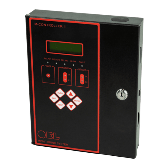
M-CONTROLLER II
MONITOR AND CONTROL SYSTEM
INSTALLATION
OPERATION AND MAINTENANCE
MANUAL
QUATROSENSE ENVIRONMENTAL LTD.
2Z0
5935 OTTAWA STREET, PO BOX 749 RICHMOND, ONTARIO CANADA K0A
PHONE: (613) 838-4005
FAX: (613) 838-4018
Web:
www.QELsafety.com
Email:
QEL@QELsafety.com
M-Controller II System Operation Manual
- 1 -
84350-201-001 Rev C
Advertisement
Table of Contents

Related Manuals for Qel M-CONTROLLER II

Summary of Contents for Qel M-CONTROLLER II
- Page 1 MONITOR AND CONTROL SYSTEM INSTALLATION OPERATION AND MAINTENANCE MANUAL QUATROSENSE ENVIRONMENTAL LTD. 5935 OTTAWA STREET, PO BOX 749 RICHMOND, ONTARIO CANADA K0A PHONE: (613) 838-4005 FAX: (613) 838-4018 Web: www.QELsafety.com Email: QEL@QELsafety.com M-Controller II System Operation Manual - 1 - 84350-201-001 Rev C...
-
Page 2: Table Of Contents
COMPUTER INTERFACE: PROGRAMMING AND AUDITING ............. 29 ..........................30 NSTALLATION MODBUS PROTOCOL SUPPORTED BY M-CONTROLLER ..............31 ........................31 ERIAL RANSMISSION ..................31 UNCTION UPPORTED BY ONTROLLER TROUBLESHOOTING HINTS ........................36 WARRANTY STATEMENT ..........................37 M-Controller II System Operation Manual - 2 - 84350-201-001 Rev C... -
Page 3: Glossary
Stub: A short wiring link branching from the main line. Voting: When more than one sensor and setpoint is assigned to a relay, then voting defines how many must reach the setpoint before the relay actuates. M-Controller II System Operation Manual - 3 - 84350-201-001 Rev C... -
Page 4: General System Overview
Windows PC software, M-View, to access the M-Controller config database. Additional RS-485 port can be programmed through Menu to either work as a Modbus RTU port for BAS or SCADA (as default) or work as a BACnet port to connect QEL BAC-Box, which supports BACnet/IP protocol. -
Page 5: Controller Specifications
24VDC nominal, range 18 to 30VDC 24VAC nominal, range 15 to 24VAC 50/60HZ Note: M-Controller II has full-wave rectifier and half-wave rectifier circuit on board for flexibility. You will damage devices if you mix half wave and full wave rectifiers on the same AC source. - Page 6 The switch can be Q-Switch or any ON-OFF switch. Analog Input 8 channel 4-20mA Analog Inputs AI-CH1 to AI-CH8 On-Board Buzzer Used for internal warning and alarm, 3700 Hz Continuous M-Controller II System Operation Manual - 6 - 84350-201-001 Rev C...
- Page 7 Strobe relay can be set to 50% duty of pulse or 100% duty ON Maximum of 750mA on the 24VDC power supply 4x RS-485 Ports with QEL Controller Protocol Remote Devices Available QEL digital transmitters, such as Q5C...
-
Page 8: Controller Installation
Backlighting is provided for the display in case of low lighting conditions. It is recommended that controllers be installed 5 feet (1.5 m) above the floor, at approximate eye level. Securely mount the M-Controller using the appropriate screws. M-Controller II System Operation Manual - 8 - 84350-201-001 Rev C... -
Page 9: Cabling
We recommend using BELDEN 9841 for communications. This wire has 120 ohms input impendence, which will eliminate RS-485 communication problems. QEL warrantees and support only covers installation with proper cable. If in doubt please contact QEL support personnel. 4.3 Connectors... - Page 10 General Guideline: Old M-Controller uses full-wave rectifier only, if the M-Controller II is supposed to replace the old M-Controller, use TB7 for input power Q5 and Q8 both have full-wave and half-wave rectifier Old M-Relay, old M-Annunciator and QRP have a full-wave rectifier only ...
-
Page 11: Rs-485 Installation
BOTH ends of the RS485 loop. Short and medium length modbus/485 loops can operate without the terminating resistor. Longer runs may require the terminating resistors. But adding a terminator dramatically increases power consumption. All QEL equipment supplies the end-of-line resistor on the circuit card. It is enabled or disabled with a shunt jumper. - Page 12 Devices and Ports: The RS-485 standard allows up to 32 devices on each communication line. The M-Controller supports up to 256 QEL devices on each RS-485 port. The M-Controller does not need to be at the end of the line. The M-Controller has four RS-485 ports for remote devices (digital sensors and I/O modules).
- Page 13 M-Controller II System Operation Manual - 13 - 84350-201-001 Rev C...
-
Page 14: Controller Supports Devices
3 relays addresses for the 3 Warning, Alarm and Failure LEDs, the 4-8 relay address is empty. For example, the 3xLEDs in the M-Annunciator #2 will be named Relay20 to Relay22 in M-Controller, Relay 23-27 are empty. Details see M-Annunciator Manual (84750-101-000) M-Controller II System Operation Manual - 14 - 84350-201-001 Rev C... -
Page 15: Controller Functions
XX-YY”, where XX is the M-Annunciator address and YY is the Waring LED, Alarm LED and Fail LED indicators. M-Logger is no longer supported by the M-Controller II 6 M-Controller Functions After the controller powers up, it will show no enabled inputs and outputs on the LCD display, as no input or output is enabled in the factory defaults settings. -
Page 16: Relay Configurations
Default is Disabled Fault Actuation When relay is set with Fault Actuation, the relay will be actuated when its assigned sensors report any fault or offline Default is Disabled M-Controller II System Operation Manual - 16 - 84350-201-001 Rev C... -
Page 17: Voting Mode
1 Off Concentration Reading: Off Concentration: For each sensor or analog input assigned, set the concentration above which the voting number will decrease 1 M-Controller II System Operation Manual - 17 - 84350-201-001 Rev C... -
Page 18: Averaging Mode
Average Off: The gas concentration at or above which the average of all the sensors assigned to this relay will cause the relay to de-actuate M-Controller II System Operation Manual - 18 - 84350-201-001 Rev C... -
Page 19: Keypad And Menu
Press key [Hush] to silence the alarmed Buzzer and Horn, and all alarmed buzzer-style relays. Key [Test] 6.3.3 For system testing, press key [Test] to force relay1-3, and all M-Relays actuate. M-Controller II System Operation Manual - 19 - 84350-201-001 Rev C... -
Page 20: Menu Mode
Menu “Unhush Buzzers” o Remove Hush status from hushed outputs, the output will be alarmed again after On Delay minutes. M-Controller II System Operation Manual - 20 - 84350-201-001 Rev C... -
Page 21: Menu "System Setting
ON and OFF at 50% duty cycle Default is 100% duty ON M-Relay: Show how many M-Relay, M-Annunciator and QPR installed in M-Annunciator: the system QRP: You can define each device address here M-Controller II System Operation Manual - 21 - 84350-201-001 Rev C... -
Page 22: Menu "Sensor Setting
Settings Description Enable: The M-Controller must be told that a sensor is attached to the control system M-Controller II System Operation Manual - 22 - 84350-201-001 Rev C... -
Page 23: Menu "Ai Setting
The switch needs to press again to switch OFF manually when it’s shown “Expired” Assigned Output: Available outputs: Relay1- Relay3, Buzzer1 – Buzzer 3, Strobe Enabled M-Relay, M-Annunciator and QRP Enabled AO-Board (AO-1 to AO-8) M-Controller II System Operation Manual - 23 - 84350-201-001 Rev C... -
Page 24: Menu "Relay 1 - 3
M-Relay Address 11: M-Annunciator Not Install Select Channel Select the channel of enabled device Relay Setting Set the channel relay configuration See relay configuration in 6.2 M-Controller II System Operation Manual - 24 - 84350-201-001 Rev C... -
Page 25: Menu "Ao Setting
Averaging Mode: See relay configuration in 6.2 On Delay (Minutes): See relay configuration in 6.2 Off Delay (Minutes): See relay configuration in 6.2 Fault Acturation: See relay configuration in 6.2 M-Controller II System Operation Manual - 25 - 84350-201-001 Rev C... -
Page 26: Menu "Assign Output
4mA output When calculated with “Base Concentration”, the value is not needed. Reading at 20mA: See above, only for AO with “Base AI mA Value” M-Controller II System Operation Manual - 26 - 84350-201-001 Rev C... -
Page 27: Menu "I/O Setting
For Factory Testing only Set Sensor port and Modbus port to be 19.2K Modbus RTU protocol with no parity. For QEL RS-485 Tester to quick test the RS-485 ports Relay 1-3 Test: Manually actuate / de-actuate Relay1 to Relay3 Buzzer & Strobe:... -
Page 28: How To Create A Database
C. Setup all relay styles. D. Setup all analog outputs. E. Setup buzzers and strobe F. Setup system settings. M-Controller II System Operation Manual - 28 - 84350-201-001 Rev C... -
Page 29: Computer Interface: Programming And Auditing
PORT ENSURE THAT THE LAPTOP IS NOT CONNECTED TO ANY POWER SOURCE. FAILURE TO FOLLOW THESE INSTRUCTIONS COULD RESULT WITH DAMAGES TO THE CONTROLLER AND OTHER DEVICES CONNECTED TO IT. M-Controller II System Operation Manual - 29 - 84350-201-001 Rev C... -
Page 30: M-View Installation
PORT ENSURE THAT THE LAPTOP IS NOT CONNECTED TO ANY POWER SOURCE. FAILURE TO FOLLOW THESE INSTRUCTIONS COULD RESULT WITH DAMAGES TO THE CONTROLLER AND OTHER DEVICES CONNECTED TO IT. M-Controller II System Operation Manual - 30 - 84350-201-001 Rev C... -
Page 31: Modbus Protocol Supported By M-Controller
(01 to 123) CRC check: xxxxH Example: to read all holding registers in M-Controller (Slave Address: 214) Query: [214] [003] [000] [000] [000] [123] [023] [206] in unsigned decimal. M-Controller II System Operation Manual - 31 - 84350-201-001 Rev C... - Page 32 Buzzer2 Statuses Status Byte Definition see 40001 40056 Buzzer3 and Strobe Buzzer3 status in High 8 bits, Strobe status in Low 8 bits Statuses Status Byte Definition see 40001 M-Controller II System Operation Manual - 32 - 84350-201-001 Rev C...
- Page 33 The Actual Reading of the Analog Input should be divided by its Decimal Decimal Position in 40079 40116 Analog Input CH2- Same as Definition in 40115 8 Reading without 40122 Decimal M-Controller II System Operation Manual - 33 - 84350-201-001 Rev C...
- Page 34 Return a description of the type of controller present at the slave address with its specification. Broadcast is not supported. Query: Slave Addr.: Function code: CRC check: xxxxH Response: Slave addr.: Function code: M-Controller II System Operation Manual - 34 - 84350-201-001 Rev C...
- Page 35 Note: Slave ID = 80H for M-Controller Slave ID = 82H for M-Controller II Slave ID = 42H for Q4-Controller II 2). Each Special Gas Type or Special Unit is composed of 3 characters. 3). Gas type and Units Definition:...
-
Page 36: Troubleshooting Hints
RS-485 bus connection Disconnect the cable to isolate the or Modbus Port has a problem problem RX/TX LED constantly ON RS-485 driver chip is Replace RS-485 driver chip damaged M-Controller II System Operation Manual - 36 - 84350-201-001 Rev C... -
Page 37: Warranty Statement
This warranty is in lieu of all other warranties, expressed or implied, and no representative or person is authorized to represent or assume for QEL any liability in connection with the sales of our products other than that set forth herein.
Need help?
Do you have a question about the M-CONTROLLER II and is the answer not in the manual?
Questions and answers