Table of Contents
Advertisement
Quick Links
Advertisement
Table of Contents

Subscribe to Our Youtube Channel
Related Manuals for Loring S35 Kestrel

Summary of Contents for Loring S35 Kestrel
- Page 1 Assembly and Installation Guide Loring S35 Kestrel Coffee Roaster...
- Page 2 This manual, along with other manuals in this series, is intended to be a guideline for the installation and use for the product lines manufactured by Loring Smart Roast, Inc. The customer is responsible for complying with all applicable regulations.
- Page 3 Stainless steel has a tendency to “seize” when over-tightened. Use care when fastening and apply food-grade anti-seize compound to fastener threads. • Loring reserves the right to change information within this document at any time without notice. Document No. 1006863 Rev A Page 3...
-
Page 4: Table Of Contents
S35 Assembly and Installation Guide Contents Introduction _________________________________________________ 6 Audience _______________________________________________ 6 Additional Documentation __________________________________ 6 Major Components, Assembled ______________________________ 7 Back View, Components, As Shipped _________________________ 8 Notes for Unpacking _______________________________________10 Uncrate the Roaster __________________________________________11 Small Parts Box __________________________________________12 Green Bean Hopper _______________________________________13 Green Bean Cart _________________________________________13 Chaff Barrel _____________________________________________14... - Page 5 S35 Assembly and Installation Guide Cyclone Connections, Assembled ____________________________37 Loosen Gas Mixer ________________________________________38 Lift Cyclone Into Position ___________________________________39 Attach Cyclone to Circulation Fan Housing _____________________40 Attach Cyclone to S-Duct ___________________________________41 Attach Purge Gate Air Cylinder ______________________________42 Attach Cyclone to Gas Mixer ________________________________43 Secure Cyclone Fasteners __________________________________44 Install Stack and Stack Hat _________________________________44 Install Cyclone, Part 2 _________________________________________47...
-
Page 6: Introduction
Product Specification Form (PSF). This form contains customer-supplied information that • is necessary in order for Loring to configure the roaster at the factory, a process that requires several weeks lead time. The customer must have completed the PSF before manufacturing of roaster can begin. -
Page 7: Major Components, Assembled
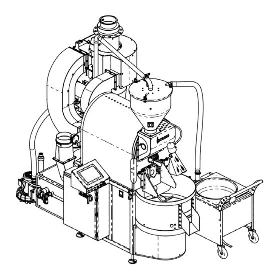
S35 Assembly and Installation Guide Major Components, Assembled The core pieces of Loring coffee-roasting equipment are the coffee roaster itself and a Green Bean Cart that is included with the S35 roaster. A separate piece of optional equipment, the Destoner, is described in a separate manual. -
Page 8: Back View, Components, As Shipped
S35 Assembly and Installation Guide Back View, Components, As Shipped Some roaster components are more easily visible prior to equipment assembly – mainly, various fans and motors. These components may be referenced during assembly instructions. (From previous page) Cooling Tray Auto Hopper Blower Consolet Electrical Enclosure... - Page 9 S35 Assembly and Installation Guide Back View, As Shipped, Continued The 45-Degree Vent Kit is an optional component. If included, it is shipped mounted to the opening on the Cooler Fan Motor Housing. 45-Degree Vent Kit Back Document No. 1006863 Rev A Page 9...
-
Page 10: Notes For Unpacking
S35 Assembly and Installation Guide Notes for Unpacking The roaster equipment is crated specifically to minimize potential damage during shipping. Use care when opening and unpacking the roaster crates, and follow the uncrating instructions for selected items. • Components are secured using nylon ties. White nylon ties are permanent, and should be left intact. -
Page 11: Uncrate The Roaster
S35 Assembly and Installation Guide Uncrate the Roaster Assembling the roaster requires clearance for forklift maneuverability on all sides. A suggested practice is to assemble the roaster in a large open space that is close to its final location, and then use a forklift to move the roaster into its final position. -
Page 12: Small Parts Box
S35 Assembly and Installation Guide Small Parts Box The Small Parts Box is inside the Chaff Barrel, and contains the Roaster Feet, the Tryer (coffee sampler for use during roasting), a Green Bean Cart Magnet, and the Stack Hat. Note that the fastener kits for the S-Duct and Cyclone are not in the Small Parts Box. These items are attached to the Cyclone itself. -
Page 13: Green Bean Hopper
S35 Assembly and Installation Guide Green Bean Hopper The Green Bean Hopper is nested inside the Green Bean Cart. Remove the Lid from the Green Bean Hopper, and use care when placing both these items on the floor to avoid damaging them. Place the Lid on the floor right side up, and place the Green Bean Hopper on the floor upside down. -
Page 14: Chaff Barrel
S35 Assembly and Installation Guide Chaff Barrel Remove the wood screws holding the Chaff Barrel in place inside the shipping crate, and move the Chaff Barrel out of the crate and onto the floor. Remove wood screws #40 Torx Bit Vacuum Tube Cut the red nylon ties that secure the Vacuum Tube to the back wall of the shipping crate. -
Page 15: S-Duct
S35 Assembly and Installation Guide S-Duct The S-Duct is bolted to the back wall and roof of the shipping crate on either end using 3 bolts at each end. Uncrating the S-Duct requires 2 people. One person should stand inside the crate, supporting the S-Duct with one hand and using the other hand to hold the bolts with a wrench, while the second person loosens the hex nuts on the exterior of the crate. -
Page 16: Mini Cyclone
S35 Assembly and Installation Guide The following steps have been adapted to make the written instructions simpler and more straightforward. Uncrating and installing the Cyclone is a multi-step process. Therefore, uncrating and assembling the Cyclone is described in the Assembly section. Mini Cyclone The Mini Cyclone is behind the Cyclone inside the shipping crate. -
Page 17: Checkpoint: Uncrating
S35 Assembly and Installation Guide Checkpoint: Uncrating At this point, the following should be true: 1. Roaster Crate #1 has all four sides and roof removed. The roaster is still on the crate skids. 2. Accessory Crate #2 has been unloaded, except for the Cyclone. Cyclone Fastener Kits An additional component, a Spare Parts Kit, is shipped with the... -
Page 18: Assemble The Roaster, Part 1
S35 Assembly and Installation Guide Assemble the Roaster, Part 1 A summary of assembly is as follows: 1. Detach roaster from crate skids and attach Roaster Feet. 2. Attach Green Bean Hopper, Vacuum Tube, and Green Bean Hopper Vacuum Hose. 3. - Page 19 S35 Assembly and Installation Guide Front Front Left View Front Front Right View Document No. 1006863 Rev A Page 19...
-
Page 20: Attach Roaster Feet
S35 Assembly and Installation Guide Attach Roaster Feet Remove the Left and Right Side Access Panels on the roaster. Left Right Unfasten the lag bolts securing the roaster Foot Blocks to the shipping crate floor. The Tool Kit contains a selection of socket wrenches. Remove rear elbow section of Cooler Air Tubing to gain access to the Foot Block in the far left corner. - Page 21 S35 Assembly and Installation Guide Roaster Feet, continued Using a forklift, raise the roaster off of the shipping crate skids. Lift the roaster using the preferred lift points. It is allowable to place the backmost fork immediately behind the main roaster body if needed.
- Page 22 S35 Assembly and Installation Guide Roaster Feet, continued Lift roaster off of the crate floor. Attach Roaster Feet. Adjust the Foot in the rear that is underneath the Utility Tray to be further off the ground than the Feet that are under the roaster body itself. Foot Block For easiest access to the Chaff Barrel Jam Nut...
-
Page 23: Attach Green Bean Hopper
S35 Assembly and Installation Guide Attach Green Bean Hopper Remove the 4 bolts attached to the opening at the top and front of the roaster body where the Green Bean Hopper will be located when attached to the roaster. Position the Green Bean Hopper on top of the roaster body. - Page 24 S35 Assembly and Installation Guide Green Bean Hopper, continued Attach the flexible Vacuum Hose to the Vacuum Hose Connection on the Green Bean Hopper. Note the differences between the two ends of the Vacuum Hose. The end that attaches to the Green Bean Cart has an operable clip with an exposed surface inside the Vacuum Hose.
- Page 25 S35 Assembly and Installation Guide Green Bean Hopper, continued Attach the Air Hose Quick Coupler. The Air Hose is already attached to the roaster body. Place the Lid on top of the Green Bean Hopper. Do not secure the Clamps until after attaching the Vacuum Tube.
-
Page 26: Attach Vacuum Tube
S35 Assembly and Installation Guide Attach Vacuum Tube Position the Green Bean Hopper Lid so that the Vacuum Tube Connection points towards the back end of the roaster. It should not point straight back, but at a slight angle to the right. Do not clamp the Lid onto the Green Bean Hopper yet. - Page 27 S35 Assembly and Installation Guide Vacuum Tube, continued Position the Vacuum Tube so that the upper end connects to the Vacuum Tube Connection on the Green Bean Hopper Lid, and the Vacuum Tube Flange Plate lines up with the Mounting Plate on the Circulation Fan Motor at the back of the roaster.
- Page 28 S35 Assembly and Installation Guide Vacuum Tube, continued The Mounting Plate on the Circulation Fan Motor has several mounting holes, but only one hole pattern matches the Flange Plate on the Vacuum Tube. Finger tighten the fasteners securing the Vacuum Tube Flange Plate to the Circulation Fan Mounting Plate. Circulation Fan Mounting Plate Mounting Holes...
- Page 29 S35 Assembly and Installation Guide Vacuum Tube, continued Fasten the top end of the Vacuum Tube to the Vacuum Tube Connection on the Green Bean Hopper Lid, using the Clamp that ships attached to the Vacuum Tube. Make sure that the O-Ring for the Clamp is seated properly between the Vacuum Tube Connection and the Vacuum Tube before tightening.
-
Page 30: Attach S-Duct To Inlet Air Opening
S35 Assembly and Installation Guide Attach S-Duct to Inlet Air Opening If the roaster shipped with the optional 45 Degree Kit (a cooler stack component), remove the 45 Degree Kit. Detach the bracket for the Magnehelic gauge by removing the bolts that secure it to the roaster body. - Page 31 S35 Assembly and Installation Guide S-Duct, continued Locate the fastener kit labeled “S-Duct to Body”, which is in a clear plastic bag attached to the Cyclone (still in the crate). Attach S-Duct to the Inlet Air Opening, including the Magnehelic gauge, mounted behind the S-Duct as shown.
- Page 32 S35 Assembly and Installation Guide S-Duct, continued At this point in the assembly process, the S-Duct, Green Bean Hopper, and Vacuum Tube have all been attached. The S-Duct is still only finger tightened. Finger tighten Back Page 32 Document No. 1006863 Rev A...
-
Page 33: Attach The Cyclone, Part 1
S35 Assembly and Installation Guide Attach the Cyclone, Part 1 Attaching the Cyclone is a multi-step process. In the first part of this task, the Cyclone is loosely attached at several key points to allow room for maneuvering until all the connections fully line up. These points are the Circulation Fan Housing, the S-Duct at both ends, and the Gas Mixer. -
Page 34: Remove Stack
S35 Assembly and Installation Guide Cyclone part 1, continued Remove Stack The Stack is shipped inside the Cyclone. It must be removed temporarily in order to lift the Cyclone into position. Note Stack orientation inside the Cyclone prior to removing it. The bolts fastening the Stack are located deep inside the Cyclone. -
Page 35: Attach Cyclone Lifting Block
S35 Assembly and Installation Guide Cyclone part 1, continued Attach Cyclone Lifting Block Locate the temporary fastener kit that is attached to the Cyclone Lifting Block. This kit contains wood screws and washers. Insert the Lifting Block into the top opening of the Cyclone, under the inner flange, with the eye bolt and webbing facing up. -
Page 36: Cyclone Connections, Exploded
S35 Assembly and Installation Guide Cyclone part 1, continued Cyclone Connections, Exploded Cyclone Circulation Fan Lifting Block Connection (temporary) Cyclone Circulation Housing S-Duct Connection Purge Gate S-Duct Air Cylinder Chaff Barrel Gas Mixer Flange Gas Mixer Back Left View, Exploded CAUTION: Do not over-tighten stainless steel fasteners, as this may cause parts to seize or fail. -
Page 37: Cyclone Connections, Assembled
S35 Assembly and Installation Guide Cyclone part 1, continued Cyclone Connections, Assembled Cyclone Lifting Block (temporary) Cyclone Circulation Housing Purge Gate S-Duct Air Cylinder Chaff Barrel Gas Mixer Back Left View, Fastened Document No. 1006863 Rev A Page 37... -
Page 38: Loosen Gas Mixer
S35 Assembly and Installation Guide Cyclone part 1, continued Loosen Gas Mixer The Gas Mixer is located in the Utility Tray at the back of the roaster. Loosen the U-Bolt Bracket holding the Gas Mixer in place, in order to allow room to maneuver when attaching the Cyclone. Removing the top elbow of the Gas Mixer provides additional room to maneuver the Cyclone into place. -
Page 39: Lift Cyclone Into Position
S35 Assembly and Installation Guide Cyclone part 1, continued Lift Cyclone Into Position Use a forklift to raise the Cyclone into position at the back of the roaster. Hook the webbing of the Cyclone Lifting Block over the forks, with the duct flanges facing outwards away from the forklift, and the Sight Glass facing to the right. -
Page 40: Attach Cyclone To Circulation Fan Housing
S35 Assembly and Installation Guide Cyclone part 1, continued Attach Cyclone to Circulation Fan Housing Use the “Cyclone to Circulation Fan” fastener kit to loosely attach the Cyclone to the Circulation Fan Housing. CAUTION: Use care when inserting and fastening the studs on the side of the Cyclone’s Circulation Fan Connection into the flange of the Circulation Fan Housing. -
Page 41: Attach Cyclone To S-Duct
S35 Assembly and Installation Guide Cyclone part 1, continued Attach Cyclone to S-Duct Use the “Cyclone to S-Duct” fastener kit to loosely attach the Cyclone to the S-Duct. Fit the Thermocouple Routing Bracket (in Small Parts Box) and the Purge Gate Air Cylinder (strapped to the Circulation Fan) on the outside of the S-Duct flange. -
Page 42: Attach Purge Gate Air Cylinder
S35 Assembly and Installation Guide Cyclone part 1, continued Attach Purge Gate Air Cylinder The Purge Gate Air Cylinder comes strapped in place with permanent white nylon ties. Using the three bolts provided, mount the Purge Gate Air Cylinder Bracket on the S-Duct side of the Cyclone / S-Duct flange. -
Page 43: Attach Cyclone To Gas Mixer
S35 Assembly and Installation Guide Cyclone part 1, continued Attach Cyclone to Gas Mixer Gas Mixer Flange Cyclone Gas Mixer Elbow Water Hose Connection Wire Ignition Wire Connections Finger tighten Gasket Use fasteners and Gasket already attached to the Gas Mixer Flange to loosely attach the Cyclone to the Gas Mixer Back... -
Page 44: Secure Cyclone Fasteners
S35 Assembly and Installation Guide Cyclone part 1, continued Secure Cyclone Fasteners After lining up Cyclone along all major connection points, fully tighten the fasteners, but do not over-tighten: • Cyclone to S-Duct • Cyclone to Circulation Fan Housing • S-Duct to Inlet Air Opening •... - Page 45 S35 Assembly and Installation Guide Cyclone part 1, continued Bracket (One bolt only) Thermocouple Clips Thermocouple Flexible Conduit Stack Thermocouples (attach to Stack) S-Duct Back View (from above right) Stack Thermocouples Stack Vacuum Tube Thermocouple Flexible Conduit Cyclone S-Duct Purge Gate Back View (from below right) Document No.
- Page 46 S35 Assembly and Installation Guide Cyclone part 1, continued The Purge Gate Air Cylinder has Thermocouple Lines already attached. Place the Thermocouple Lines into the Hose Clips. Purge Gate S-Duct Air Cylinder S-Duct Stack Thermocouple Clips Purge Gate Air Cylinder Circulation Fan Circulation Fan Page 46...
-
Page 47: Install Cyclone, Part 2
S35 Assembly and Installation Guide Install Cyclone, Part 2 The remaining connections on the Cyclone are: • Water Lines (Chaff Quench Hoses) • High Temperature Cutoff Switch (Spade Connectors) • Ignition Wire Connection, BCU or DSI (Liquid Tight Conduit) • Chaff Barrel Document No. -
Page 48: Final Roaster Assembly
S35 Assembly and Installation Guide Final Roaster Assembly Attach Auto Hopper Blower Auto Hopper Blower Hose fasteners ship attached to the Hose itself. Mini Cyclone Hose Port (connects to Auto Hopper Blower Hose) Electrical Connectors are inside box Auto Hopper Blower fasteners ship attached to the eye bolt on the Auto Hopper Blower Housing. - Page 49 Utility Tray. Connect the wire conduit to the motor’s electrical box, but leave the wires themselves disconnected. The Loring Field Service Technician will complete this part of the installation as part of system commissioning. Document No. 1006863 Rev A...
-
Page 50: Attach Mini Cyclone
S35 Assembly and Installation Guide Attach Mini Cyclone Attach the Mini Cyclone to the end of the Vacuum Tube using the Clamp and O-Ring that is attached to the Vacuum Tube. Attach the Auto Hopper Blower Hose to the Auto Hopper Blower, using fasteners that ship already attached. - Page 51 S35 Assembly and Installation Guide Mini Cyclone, continued When attached, the Mini Cyclone should appear as shown. Mini Cyclone Auto Hopper Blower Hose Back Right View Back Auto Hopper Blower Document No. 1006863 Rev A Page 51...
-
Page 52: Move Roaster To Final Location
S35 Assembly and Installation Guide Move Roaster to Final Location At this point, the roaster is ready to be moved to its final location in preparation for final installation (stack and utility hookups). Use a forklift and lift from the center of the roaster body. Do not place fork lift points under the Cooling Tray area or far to the back under the Utility Tray. -
Page 53: Chaff Barrel
Obtain a compressed air supply that meets the specifications listed in the Pre-Installation and Site Preparation Guide. Complete this task prior to the final site commissioning visit from the Loring Field Service Technician. Contact Loring for guidance on selecting and ordering suitable equipment. -
Page 54: Install The Roaster
However, final IP configuration cannot be done until the roaster is powered on for the first time by a Loring Field Service Technician, during site commissioning. Note: The roaster will operate without being connected to a computer network, but this will limit technical support, and will prevent the roaster from sending Roast Data reports at the end of each roast, as well as Alarm Status and Alarm History email reports. -
Page 55: Air, Water, And Gas Connections
S35 Assembly and Installation Guide Air, Water, and Gas Connections Roaster Back Green Bean Cart Water Hookup Compressed Air Hookup 1/2" FNPT Connection 1/2" FNPT Connection Front Natural Gas or Propane Hookup 3/4" FNPT Connection Back Front Water Document No. 1006863 Rev A Page 55... -
Page 56: Hot Air Exhaust Vent Connection
S35 Assembly and Installation Guide Hot Air Exhaust Vent Connection Stack 8" minimum inside diameter Back Refer to the Pre-Installation and Site Preparation Guide for additional system specifications and operating temperatures. Front Back Front Page 56 Document No. 1006863 Rev A... -
Page 57: Cooling Air Exhaust Vent Connection
S35 Assembly and Installation Guide Cooling Air Exhaust Vent Connection Back 8" minimum diameter Front Back Front Document No. 1006863 Rev A Page 57... -
Page 58: Electrical And Network Connections
S35 Assembly and Installation Guide Electrical and Network Connections Local Area Back Network (LAN) Inlet Front Electrical Enclosure Power Cable Inlet Ground Lug Ethernet Switch Fusable Disconnect Customer can use any unused ports Left View Page 58 Document No. 1006863 Rev A... -
Page 59: Position Final Items
S35 Assembly and Installation Guide Position Final Items The Green Bean Cart can be positioned for daily operations. Position the Destoner, if used. The Chaff Barrel fits underneath the Cyclone. Push down on Chaff Barrel to compress the wheel springs. While continuing to press down, roll the chaff barrel to fit it under the Cyclone. Use the Chaff Barrel clamp to hold the Chaff Barrel in place. -
Page 60: Next Steps
Next Steps After all assembly and installation tasks described in this manual have been completed, the customer should contact Loring to schedule a site visit and system commissioning from an authorized Loring Field Service Technician. System commissioning includes onsite customer training. -
Page 61: Manufacturer Contact Information
Manufacturer Contact Information This equipment is manufactured by: Loring Smart Roast, Inc. 3200 Dutton Ave #413 Santa Rosa, CA 95407 (707) 526-7215 For questions, please contact Loring Customer Support: www.loring.com/support (707) 526-7215 x 217 support@loring.com Document No. 1006863 Rev A Page 61...
Need help?
Do you have a question about the S35 Kestrel and is the answer not in the manual?
Questions and answers