
Subscribe to Our Youtube Channel
Related Manuals for Remington AIR RA2021


Summary of Contents for Remington AIR RA2021
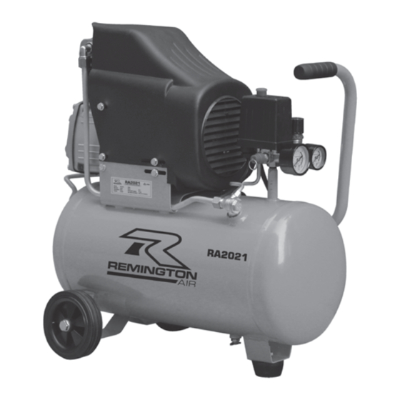
- Page 1 WORKSHOP SERIES PORTABLE COMPRESSOR FOR GENERAL LIGHT DUTY TASK AROUND THE HOME MODEL NO. RA2021 Read this material before using this product. Failure to do so can result in injury. SAVE THIS MANUAL www.remingtonair.co.nz...
- Page 2 TECHNICAL INFORMATION CONTENTS Specifications Air Compressor RA2021 General Safety Instructions 4 – 6 No Load Speed 2800 RPM Free Air Delivery (FAD) 95 L per minute* Specifi SUGGESTED APPLICATIONS Operating Instructions 9 – 15 You may use some light duty air tools with this compressor.
- Page 3 INTRODUCTION Dear Customer, Thank you for purchasing this compressor which has passed through our extensive quality assurance processes. Every care has been taken to ensure that it reaches you in perfect condition. However, in the unlikely event that you should experience a problem, or if you require any assistance please do not hesitate to contact us;...
- Page 4 LUBRICATION OF COMPRESSOR WORK AREA Before attempting to operate this air compressor Work areas and benches should be kept tidy. the transport plug must be removed, thrown out Cluttered benches and work areas can cause and replaced with the oil breather. Check the accidents.
- Page 5 DO NOT ABUSE DISCONNECT AIR COMPRESSOR THE POWER CORD Ensure that the air compressor is disconnected from the mains supply when not in use, before Never yank or pull on the power cord to disconnect servicing, lubricating, making adjustments or it from the mains supply socket.
- Page 6 CHECK DAMAGED PARTS Eye Protection The use of safety goggles is highly recommended Before using the air compressor it should be (normal glasses are not sufficient for eye carefully checked to determine that it will operate protection) when using an air compressor. Prescription glasses do not have safety lenses.
- Page 7 ELECTRICAL DATA IMPORTANT This air compressor is fitted with a sealed electrical connection plug that is compatible with the mains power supply for Australia / New Zealand and meets the requirements of international standards. This air compressor must be connected to a supply voltage that is equal to that stated on the rating label.
- Page 8 PIC. 1 COMPONENTS AND CONTROLS Pic. 1 1.Oil fill and breather 2. Oil sight glass 3. Oil drain bolt 4. Rear handle 5. Tank 6. Wheels 7. Tank drain tap 8. Rubber stopper 9. Safety Valve 10. Tank pressure gauge - large 11.
- Page 9 OPERATING INSTRUCTIONS Unpacking PIC. 2 Carefully unpack your air compressor. This air compressor is bulky and heavy, two (2) person lift required. Dispose of all packing material in an Screw in oil environmentally responsible manner. breather Assembly Your air compressor requires minor assembly before initial operation.
- Page 10 RUBBER STOPPER PIC. 5 To attach the rubber stoppers to the bracket located on the bottom of the tank; 1. Undo the nut and remove the washer. 2. Push through the bracket and replace the washer. 3. Tighten the nut, Pic. 5 WHEELS PIC.
- Page 11 AIR FILTER PIC. 7 The supplied air filter must be used. Failure to do so may result in irreparable damage and will void the warranty, Pic. 7 To install; 1. Carefully screw supplied air filter into the threaded hole on the top of the pump head. This only needs to be done up by hand.
- Page 12 RUNNING IN YOUR NEW AIR USING THE AIR COMPRESSOR COMPRESSOR Before starting run through this simple list; Before running in ensure that the following has 1. Transport plug removed and discarded, see been completed; Pic. 2, page 10. 1. The transport plug has been removed and 2.
- Page 13 PIC. 9 The configuration of tools and accessories can be varied to suit your particular requirements. A basic recommended set up is shown in Pic. 9. When you have finished using your air compressor follow these simple steps; 1. Turn your air compressor OFF, using the ON/ OFF switch.
- Page 14 ADJUSTING THE PRESSURE PIC. 10 To adjust the outlet air pressure, use the red coloured regulator knob and check the pressure on the outlet pressure gauge, Pic. 10. Regulator If the pressure needs to be lower, turn anti clockwise. If the pressure needs to be higher, turn clockwise.
- Page 15 AIR TAP PIC. 12 Rotate tap handle to open/close Pic. 12 start/stop the air supply to your attached tool The air tap will need to be opened to allow the air Closed tap Open tap to flow to the attached air tool. To open air tap rotate the handle so that it lines up with the fittings and hose, not supplied.
- Page 16 MAINTENANCE Daily: Before use 1. Seal the tank drain tap, see page 16, Pic.13. PIC. 14 2. Check the oil level, see page 10, Pic. 4. 3. Check safety valve operation, see page 15, Pic.11 After use Remove oil 1. Open the tank drain tap, see page 16, Pic.13. drain bolt and drain used oil 2.
- Page 17 PARTS DIAGRAM Part Description SMG Part No. Part Description SMG Part No. Cylinder Head 95 BRC95CH Pressure Gauge Small 95 BRC95OPG Oil Breather 95 BRC95OB One Way Valve 95 BRC95OWV Sight Glass Seal 95 BRC95OLSG Rubber Handle Grip 95 BRC95TH Sight Glass 95 BRC95OLSG Drain Tap...
- Page 18 WARRANTY As part of an on-going commitment to excellence in Warranty does not cover any incidental, indirect or product support, Euroquip offers a comprehensive consequential loss, damage or expense that may product warranty program. result from any defect, failure or malfunction of a product.
- Page 20 REMINGTON AIR...
Need help?
Do you have a question about the AIR RA2021 and is the answer not in the manual?
Questions and answers