Advertisement
Quick Links
714-8INT/714-16INT ZONE EXPANDERS
Installation Guide
Z1+
Z5+
Tens Ones
Z1–
Z5–
KYPD LX
Z2+
Z6+
J2
Z2–
Z6–
Z6+
TXD
RED
Z3+
Z7+
YEL
Z3–
Z7–
RED
GRN
Z4+
Z8+
BLK
Z4–
Z8–
J3
J5
J7
J10
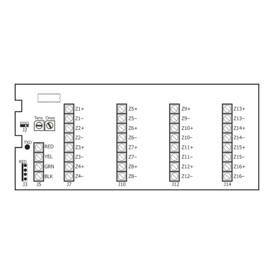
Figure 1: 714-8INT/714-16INT
Zone Expander
DESCRIPTION
The 714-8INT and 714-16INT provide
an additional eight or sixteen
supervised zones for connecting
burglary and nonpowered fire alarm
initiating devices to the panel.
The zone expanders provide
terminal strips, a jumper for LX-
Bus or Keypad Bus designation, a
transmit data LED to indicate panel
communication.
Compatibility
•
XT30INT Panels
•
XR150INT/XR550INT Series
Panels
What is Included?
•
One 714-8INT or 714-16INT Zone
Expander
•
Sixteen or thirty-two 1K Ohm
Resistors
•
One Model 340 Enclosure with
Lock and Key
1
Z9+
Z13+
Z9–
Z13–
Z10+
Z14+
Z10–
Z14–
Z11+
Z15+
Z11–
Z15–
Z12+
Z16+
Z12–
Z16–
J12
J14
2
3
PROGRAM THE PANEL
Refer to the panel programming guide as needed.
Reset the panel. If you are using an XT panel, enter 665
1.
(PRO) at a keypad; if you are using an XR panel, enter 6653
(PROG) at a keypad. Press CMD.
In ZONE INFORMATION, program the expansion zones as
2.
any of the panel's burglary or fire zone types. You can also
program zones as an Arming (AR) zone type when they are
being used with key switches.
3.
Press CMD until STOP displays. Press a top row select key or
area to save programming.
MOUNT THE ENCLOSURE
Mount the enclosure in a secure, dry place. It is not necessary
to remove the zone expander circuit board when installing the
enclosure.
The enclosure can be surface or flush mounted using the holes
provided. Each of the four sides have dual 1/2 in. and 3/4 in.
conduit knockouts for running wires out of the enclosure.
WIRE THE ZONE EXPANDER
The zone expanders provide a 3-pin header with jumper used to
determine the connection type.
To connect the expander to the Keypad Bus, place the jumper
across the two leftmost pins.
To connect the expander to the LX-Bus, place the jumper across
the two rightmost pins. For more information, refer to Figure 2.
Connect to the LX-Bus
To wire the expander, join the red, yellow, green, and black wires
to a 4-wire harness and connect it to the LX-Bus.
Connect to the Keypad Bus
1.
Connect the red, yellow, green, and black wires to panel
Terminals 7, 8, 9, and 10 respectively.
2.
Observe polarity and wire the zones.
Note: You may use the header instead of the terminal to connect
the expander to the panel.
Advertisement

Related Manuals for DMP 714-8INT

Summary of Contents for DMP 714-8INT
- Page 1 Press CMD until STOP displays. Press a top row select key or DESCRIPTION area to save programming. The 714-8INT and 714-16INT provide an additional eight or sixteen supervised zones for connecting MOUNT THE ENCLOSURE burglary and nonpowered fire alarm initiating devices to the panel.
- Page 2 ZONE STATE ZONES Normal 1k Ohms Normal 3.3k Ohms Normal 4.7k Ohms Open Open Open 2k Ohms 6.6k Ohms 9.4k Ohms Tamper Tamper Tamper >2k Ohms >6.6k Ohms >9.4k Ohms Table 1: Zone State Specifications 714-8INT/714-16INT INSTALLATION GUIDE DIGITAL MONITORING PRODUCTS...
- Page 3 SET THE ZONE EXPANDER ADDRESS 714-8INT/714-16INT Point Zone Expanders use two rotary switches (TENS and ONES) to set the address. For keypad bus addresses, the ONES switch must be set to a starting address that communicates the status of the first four zones (Z1 through Z4) on the expansion module. The next consecutive keypad address is automatically used to communicate theV status of the next four zones (Z5 through Z8), etc.
- Page 4 DMP recommends using 18 or 22 AWG for all LX-Bus and Keypad Bus connections. The maximum wire distance between any module and the DMP Keypad Bus or LX-Bus circuit is 1,000 feet. To increase the wiring distance, install an auxiliary power supply, such as a DMP Model 503INT.
Need help?
Do you have a question about the 714-8INT and is the answer not in the manual?
Questions and answers