Table of Contents
Advertisement
Quick Links
Advertisement
Table of Contents

Related Manuals for Sewhacnm SI 560A


Summary of Contents for Sewhacnm SI 560A
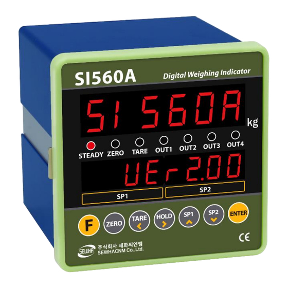
- Page 1 SI 560A DIGITAL INDICATOR USER MANUAL MANUAL Ver. 4.00 PROGRAM Ver. 4.00...
-
Page 2: Table Of Contents
INDEX 1. BEFORE INSTALLATION ............4 2. INTRODUCTION............... 5 2-1. Introduction ..................... 5 2-2. Feature ....................... 5 2-3. Components ....................5 3. SPECIFICATION ................ 6 3-1. Specification ....................6 3-2. Front ........................7 3-3. Rear panel ...................... 10 4. INSTALLATION ............... 11 4-1. - Page 3 7. ERROR & TROUBLESHOOTING .......... 63 7-1. Error & troubleshooting during Load cell installation ....63 7-2. Error code ...................... 64 7-3. Error and troubleshooting ............... 65...
-
Page 4: Before Installation
This manual may be changed as the version is upgraded, without previous notice. 1-3. Inquiries If you have any kinds of inquiries for this model, please contact your local agent or Head Office. Head office : SEWHACNM CO., LTD. Website : http://www.sewhacnm.co.kr Email : sales@sewhacnm.co.kr... -
Page 5: Introduction
2-1. Introduction Thank you for your choice of SI560A Industrial Explosion proof indicator. This “SI 560A” model has various external interface: serial communication (Modbus available), analog output and RS232c/RS422/RS485 Communication, BCD in/out to select option for user convince and environment. -
Page 6: Specification
SPECIFICATION 3-1. Specification Content Specification Display Resolution 1/20,000 Internal Resolution 1/2,000,000 (±1,000,000) Input Sensitivity Min 0.1µV/V Load cell Max Signal Input Max 3.2mV/V input Analog Voltage signal Load cell Excitation DC +5V A/D Conversion Digital Sigma-Delta Method convert Decimal Point 0, 0.0, 0.00, 0.000 content Zero... -
Page 7: Front
3-2. Front 3-2-1. Display and key pad ① Display 1 : Number/word display 6 digits red FND ② Condition(lamp) STEADY : When the weight is stable, ON. ZERO : When the current weight is zero, ON. TARE : When the “TARE” function is set, ON. OUT1 : When connected with OUT1(relay), ON OUT2 : When connected with OUT2(relay), ON OUT3 : When connected with OUT3(relay), ON... - Page 8 3-2-2. Key operation 1. Press this key 4times, within 3secs, enter to “SET-UP” mode. 2. Press this key during 4secs, enter to “Hidden function” mode. 3. Cancel or ESC. 1. Make weight value to Zero. 2. Enter to P/N setting at the SP value setting stage 1.
- Page 9 3-2-3. Key combination SP3 Set value setting SP4 Set value setting If the Printer is installed, You can print out the “Sub-total data”. (Sub-total data cannot be displayed). If the Printer is installed, You can print out the “Grand-total data”. (GRAND-total data cannot be displayed.) - Max accumulated weighing count : 999,999times - Over 999,999times ...
-
Page 10: Rear Panel
3-3. Rear panel ③ ⑦ ⑧ ⑤ ① ② ④ ⑥ ① DC(basic)/AC(option) power input terminal ② External Input terminal 1 : zero voltage point ③ External Input terminal 2 : zero voltage point ④ Serial Interface 1 (RS422/485) ⑤ Serial Interface 2 (RS232) ⑥... -
Page 11: Installation
4. INSTALLATION 4-1. External Dimension (Unit: mm) 4-2. Cutting Size (Unit: mm) -
Page 12: Load Cell Installation
4-3. Load cell Installation Load Cell Wire Connection (In case of SEWHACNM‟s Load cell) It depends on the manufacturer of load cell, please check the specification. EXC+ White EXC- Green SIG+ Blue SIG- Yellow SHELD 1. When you setup the Load cell, if EXC+ and EXC- have a short circuit, It may cause damage in the indicator. -
Page 13: External Output
4-4. External output Each output relay function can be changed on Function number 233~236. Connected with zero voltage point INDICATOR Equipment IN1~4 Terminal component - Top, Bottom - COM : Input common terminal(V+ : 12V DC) - Ⅰ1~Ⅰ4 : Input signal(Output relay: zero voltage point –relay or switch signal) 4-5. - Page 14 4-5-2. RS485 RS485 interface is strong for electrical noise, and it is available for below 1km distance. The RS422 is half-duplex communication, it has slower speed than RS422. RS485 can connect to external equipment such as PC, PLC, printer or etc. with multiple use. (Max 32ea indicator) INDICATOR Equipment...
-
Page 15: Relay Outputs
4-6. Relay outputs Relay output 4EA(NO: Normal Open) : User can change relay output setting on function number 226~229. 4-6-1. Relay specification Coiling Rating 12VDC Contact Ratings 1A 24VDC 4-6-2. Relay output inner circuit Terminal block - OC : Output common - O1~O4 : Output (Zero voltage relay output) -
Page 16: Analog Output
4-7. Analog output <①Switch picture> ※ How to select analog output (Iout or Vout) ① User can select the Iout or Vout on the inner interface board when they disassembled indicator. ② Enter the HF13 and select the analog current output interface and 00 : I-out or 01 : V-out. - Page 17 4-7-2. Analog voltage output interface (0~10V) This output card converts weight value to Analog output signal (0~10V) and transfers to external devices(Recorder, PLC), controlled by voltage output. Output voltage 0~10VDC output Accuracy 1/1,000 - In calibration mode or Ad-Err condition, analog output will not activated. - If the output is deactivated, the last output signal value will be hold until next activation.
-
Page 18: Setup
5. SETUP 5-1. Calibration Calibration is the process of adjusting weight balance between "Real Weight" on the Load Cell and "Displayed weight of Indicator". When you replace Load Cell or Indicator, you have to do Calibration process once again. Before start to the calibration mode, Please turn on the indicator and preheat about 15 min. - Page 19 STEP 2. Unit Setting : Adjust decimal point : Adjust number Input Max. weight : Save and move to next step : Cancel and move to previous step EX : If you want to set Max capacity as 50.00kg (Division: 0.01kg), input 50. STEP 3.
- Page 20 STEP 4. Measuring the “DEAD” Weight of Weighing Scale : Save and move to next step : Cancel and move to previous step Make sure your scale is EMPTY ※ When “Err-A” displays, remove the things on the scale part, external noise or vibration and carry out calibration again.
- Page 21 5-2. Simulation Calibration (Calibrate without Test weight) With this “Simulation Calibration Mode” you can make simple calibration without any “TEST weight” This calibration mode uses “Load cells‟ max capacity” and “Max Output Rate(mV)”, so the weight adjustment degree might be less than “Test weight Calibration”. The guaranteed resolution of this “Simulation Calibration”...
- Page 22 STEP 2. Unit Setting : Adjust decimal point : Adjust number Input Max. weight : Save and move to next step : Cancel and move to previous step MODEL: xxxxx The maximum capacity means that added all CAPA: 20kg installed load cells. R.O: 1.429mV/V ※...
- Page 23 STEP 4. Measuring the “DEAD” Weight of Weighing Scale ※ : Save and move to next step ※ : Cancel and move to previous step Make sure your scale is EMPTY ※ When “Err-A” displays, remove the things on the scale part, external noise or vibration and carry out calibration again.
-
Page 24: Function Setting
5-3. Function setting Function setting could set the indicator to operate perfectly with surrounding condition. 5-3-1. Starting F-FUNCTION Mode Press “F” key for 4 times within 3 seconds. : Adjust decimal point : Adjust number : Move to function number Save function value : Cancel and move to previous step Display Information... - Page 25 5-3-2. F-Function List Subject Default Content Equipment No. setting 01~99 (ID No.) 00 : Normal mode Weight–back up mode 01 : Weight back up mode(Zero) 02 : Weight back up mode(Zero & Tare) 00 : Manual: Whenever “Print” key input Weighing data save method 01 : Auto: At every steady states &...
- Page 26 Subject Default Content Zero key operation range 00: Active within 2% of max capacity 01: Active within 5% of max capacity 02: Active within 10% of max capacity 03: Active within 20% of max capacity 04: Active within 50% of max capacity 05: Active within 100% of max capacity 06: No limit Tare key operation range...
- Page 27 Subject Default Content Minus (-) mark display 00 : Use 01 : No display UNPASS/OVERLOAD state, 00 : Display (After display UP or OL, current weight display weight will display repeatedly) 01 : No display (Display UP or OL repeatedly) Weighing mode 00 : Disuse 04 : Packer Mode 1...
- Page 28 Subject Default Content Finish relay output delay 00 ~ 99(Unit : 0.1sec) time 00 : Finish Relay output at steady state 20 : Finish Relay output after 2.0 seconds 99 : Finish Relay output after 9.9 seconds Finish relay output time 00 ~ 99(Unit : 0.1sec) 00 : Relay output until the weight is lower than near zero range...
- Page 29 Subject Default Content Format in stream mode 00 : Format 1 (18byte) (Serial port 1) 01 : Format 2 (21byte) 02 : Format 3 (17byte) 03 : Format 4 (22byte) Transference in stream mode 00 : Continuously (Serial port 1) 01 : Single time on every steady state 02 : Single time at the first steady point 03 : Single time output after weighing finish...
- Page 30 Subject Default Content Transference in stream mode 00 : Continuously (Serial port 2) 01 : Single time on every steady state 02 : Single time at the first steady point 03 : Single time output after weighing finish 04 : When input “F” key Print mode 00 : Continuously 01 : Each...
- Page 31 ◆ Weighing Mode 1 – Limit mode (Function 223-01) - Relay “ON” when weight reaches set value WEIGHT Near Zero Zero Time set Time Contents Finish Relay Output Delay Time (Function 239) When Function 103-3 or 103-6, save the date after t1 time. Relay output Relay Condition...
- Page 32 ◆Weighing mode 2 – Checker mode (Function 223-02) WEIGHT Over Over Pass Under Under Near zero Under out Over out Pass out Error out Weight set Under Over Time set Time Contents Weight Judge Delay Time (Function 241) When Function 103-3 or 103-6, save the date after t1 time. Weight Judge Time (Function 243) Error relay out delay Time (Function 244) Error relay out Time (Function 245)
- Page 33 ◆Weighing mode 3 – Packer mode (Function 223 – 03) WEIGHT Near Zero Zero Tare Input Start Input Weight set Set point Drib Free fall Time set Time Contents Finish Relay Output Delay Time (Function 239) When Function 103-3 or 103-6, save the date after t1 time. Finish Relay Output Time(Function 240) Relay output Relay...
- Page 34 5-3-3. Hidden function ※ How to enter hidden function mode <Password input key> Press “F” key for 4 seconds : Number 1 Enter the password (Default: 1111) : Number 2 : Number 3 : Number 4 : Number 5 <Proceed and cancel key> : Increase the number : Move to function number Save function value...
-
Page 35: Set-Point Setting
HF14 Adjust Analog minimum output value 0.00 (Move decimal point) Adjust Analog maximum output value 0.00 revision HF15 (-, +) * Adjust ± value to correct error Function list factory reset FUNSET Select key, HF16 “NO(Cancel the reset)”, “YES(Do the reset)” and press HF17 Simulated calibration value enter OrnU... - Page 36 5-4-2. SP2 or Over : Adjust decimal point : Adjust number : Save Input set value : Cancel and move to previous step ※ When weighing mode is set as checker mode, Input Product No. SP1 value is going to be the Over weight. ※...
- Page 37 5-4-4. SP4 : Adjust decimal point : Adjust number : Save Input set value : Cancel and move to previous step ※ SP4 is for Limit mode, Packer mode. Input Product No. ※ You cannot set this value more than Max. capacity.
- Page 38 5-5-2. Delete Grand-total Press “F” key 4 times in 3 seconds : Save : Cancel and move to previous step ※ Grand-total is not displayed on display. ※ User can check grand-total through Cancel delete Proceed delete communication and print.
-
Page 39: Test Mode
5-6. Test mode Disconnected all indicator and equipment when do the test mode. Press the key 4 times sequentially. Display shows Enter the test mode 1, press key. Enter the test mode 2, press key. Display shows it entered test mode.. User can check indicators conditions use the below keys. - Page 40 5-6-1. Checking load cell input number In test mode 1, press the value shows. ※ You can check the load cell analog value. (Display range : -1,048,575 ~ 1,048,575) ※ If analog value is changing even though there are nothing on the weighbridge, or If analog value is not changing when you load some weight on weighbridge, It might be malfunction of load cell or analog board inside indicator.
- Page 41 5-6-4. Key pad check mode You can check the key condition when enter the key. 1) In test mode press the key, display shows 2) Except key, showing every numbers with same keys. 3) Press key, back to display. DISPLAY DISPLAY DISPLAY 5-6-5.
- Page 42 5-6-7. Analog value check (Analog Output) 4~20mA, 0~10V 1) In test mode 2, press display shows. 2) Can be simulated by virtually printing a value on the indicator from 0 (4 mV, 0 V) to 100 (20 mV, 10 V). 3) If the analog output is between 4 and 20 mA, the display shows A and the analog output, If 0 to 10 V, the display shows V.
- Page 43 5-6-8. Serial port 1 interface check mode 1) In test mode 2, press key, display shows. 2) Connect with PC or other devices through serial interface and check the transference and receipt.(Except 3) At the normal operation, LED will blink one time. 4) Press key, back to display.
-
Page 44: Communication Data Format
6. Communication Data Format 6-1. Simplex (Stream mode) 6-1-1. Format 1 (Excluding ID number) – 18 byte Classification Contents Header1 (2Byte) OL : Current weight is over than max capacity weight. ST : Stable weight US : Unstable weight Header2 (2Byte) NT : NET-WEIGHT(Real weight which is excluded tare weight) GS : GROSS-WEIGHT (If tare is set, it is included real weight and tare weight.) - Page 45 6-1-2. Format 2 (Including ID number) – 21 byte Classification Contents ID Number (2Byte) ID Number Header1 (2Byte) OL : Current weight is over than max capacity weight. ST : Stable weight US : Unstable weight Header2 (2Byte) NT : NET-WEIGHT(Real weight which is excluded tare weight) GS : GROSS-WEIGHT (If tare is set, it is included real weight and tare weight.) Sign (1Btye)
- Page 46 6-1-3. Format 3 (Including ID number) – 17 byte Classification Contents STX (1Byte) Start of Text ID Number (2Byte) ID Number Header1 (1Byte) OL : Current weight is over than max capacity weight. ST : Stable weight US : Unstable weight Header2 (1Byte) NT : NET-WEIGHT(Real weight which is excluded tare weight) GS : GROSS-WEIGHT...
- Page 47 6-1-4. Format 4 (Including ID number) – 22 byte Classification Contents Header1 (2Byte) OL : Current weight is over than max capacity weight. ST : Stable weight US : Unstable weight Header2 (2Byte) NT : NET-WEIGHT(Real weight which is excluded tare weight) GS : GROSS-WEIGHT (If tare is set, it is included real weight and tare weight) ID Number (1Byte)
- Page 48 6-1-5. Format 5 (P/N, Judgement weight, Weight transmission, For checker mode) – 15 byte Classification Contents STX (1Byte) Start of Text Part Number (2Byte) Header1 (1Byte) N : No judgement U : Under P : Pass O : Over Sign (1Btye) Sign Weight Data (7Byte) Weight data...
- Page 49 6-2. Command Mode In “Command Mode”, Indicator will recognize the receipt of Order based on 02h(STX) and 03h(ETX) signal, and transfers 06h(ACK), 15h(NAK). 6-2-1. Read command Subject Command Length of transmission data Current Weight STX ID RCWT ETX 22 byte Current data STX ID RCWD ETX 46 byte...
- Page 50 6-2-2. Write Command Length of transmission Subject Command data Zero STX ID WZER ETX 8 byte Tare STX ID WTAR ETX 8 byte Tare Reset STX ID WTRS ETX 8 byte Hold STX ID WHOL ETX 8 byte Hold Reset STX ID WHRS ETX 8 byte Print...
- Page 51 6-2-3. Read Command Detail Current Weight ASCII : STX ID(2byte) RCWT ETX HEX : 02 30 31 52 43 57 54 03 STX ID RCWT State1(1byte) State2(1byte) P decimal point(1byte) +/-(1byte) Current weight(7byte) Weight unit(2byte) ETX Response State1 : O(Over Load) , S(Steady), U(Unsteady) State2 : N(Net weight), G(Gross weight) Ex) Steady(S), TARE not used(N), 0.000kg Indicator memory data...
- Page 52 Grand Total data ASCII : STX ID(2byte) RGRD ETX HEX : 02 30 31 52 47 52 44 03 STX ID RGRD P decimal point(1byte) the no. of weighing (6byte) Accumulated Response weight(10byte) unit(2byte) ETX Ex) the no. of weighing : 10 , Accumulated Weight : 10.000kg Sub-total data ASCII : STX ID(2byte) RSUB ETX HEX : 02 30 31 52 53 55 42 03...
- Page 53 Current date data ASCII : STX ID(2byte) RDAT ETX HEX : 02 30 31 52 44 41 54 03 Response STX ID RDAT Current Date(6byte) ETX Date : Aug 12 ,2014 Tare data ASCII :STX ID(2byte) RTAR ETX HEX : 02 30 31 52 54 41 52 03 Response STX ID RTAR P decimal point(1byte) +/-(1byte) TARE value(7byte) ETX EX) TARE : 2.000kg...
- Page 54 SP 3 data ASCII : STX ID(2byte) RSP3 ETX HEX : 02 30 31 52 53 50 33 03 Response STX ID RSP3 P decimal point(1byte) SP 3 value (7byte) ETX Ex) SP3 value: 7.000kg SP 4 data ASCII :STX ID(2byte) RSP4 ETX HEX : 02 30 31 52 53 50 34 03 Response STX ID RSP4 P decimal point(1byte) SP 4 value (7byte) ETX...
- Page 55 Current weight, Input, Output state ASCII :STX ID(2byte) RWRS ETX HEX :02 30 31 52 57 52 53 03 STX ID RWRS P decimal point(1byte) +/-(1byte) current weight(7byte) Response INPUT1,2,3,4(4byte) OUTPUT1,2,3,4(4byte) ETX (ON : 1 OF : 0) Ex) Weight : 7.000kg, INPUT : IN1,IN3, OUTPUT : OUT2,OUT4 Current P/N transmit ASCII : STX ID(2byte) RPNO ETX HEX : 02 30 31 52 50 4E 4F 03...
- Page 56 6-2-4. Write Command Detail Zero (same as “ZERO” key) ASCII : STX ID(2byte) WZER ETX HEX : 02 30 31 57 5A 45 52 03 Response Normal : STX ID ACK ETX Error : STX ID NAK ETX Tare ASCII : STX ID(2byte) WTAR ETX HEX : 02 30 31 57 54 41 52 03 Response Normal : STX ID ACK ETX Error : STX ID NAK ETX...
- Page 57 ASCII : STX ID(2byte) WSTP ETX HEX : 02 30 31 57 53 54 50 03 Response Normal : STX ID ACK ETX Error : STX ID NAK ETX Date Setting ASCII : STX ID(2byte) WDAT data(6byte) ETX Ex) Date : Aug 12 ,2014 Response Normal : STX ID ACK ETX Error : STX ID NAK ETX...
- Page 58 SP 4 setting ASCII : STX ID(2byte) WSP4 SP4 value(7byte) ETX Ex) SP4 : 8.000kg (decimal point 0.000) Response 정상 : STX ID ACK ETX, 오류 : STX ID NAK ETX SP 1,2,3,4 setting ASCII : STX ID(2byte) WSPA SP1 value (7byte) SP2 value (7byte) SP3 value (7byte) SP4 value (7byte) ETX Ex) SP1 5.000kg SP2 6.000kg SP3 7.000kg SP4 8.000kg Response...
- Page 59 Change SP1,2,3,4 set point of entire P/N ASCII : STX ID(2byte) WFTD P/N(2byte) SP1 value(7byte) SP2 value (7byte) SP3 value (7byte) SP4 value (7byte) ETX Ex)SP1 5.000kg, SP2 6.000kg, SP3 7.000kg, SP4 8.000kg, P/N 17 (Random number) Response Normal : STX ID ACK ETX Error : STX ID NAK ETX How to Calculate Check Sum.
-
Page 60: Modbus Memory Map
6-3. Modbus memory map - RO : Read Only - RW : Read Write - Each P/N’s set point can’t over max capacity of Indicator. ex)35.00kg = 3,500 (0xDAC) - When you input date and time, it should be 6digit. ex) 1st January 2014 = 140101 (0x22345) 15(H) : 50(M) : 17(S) = 155017 (0x25D89) - Refer the memory register for regarding Lamp, Error, Digital Input,... - Page 61 6-3-2. Digital input register 1bit 2bit 3bit 4bit 5bit 6bit 7bit 8bit IN 1 IN 2 IN 3 IN 4 6-3-3. Lamp register 1bit 2bit 3bit 4bit 5bit 6bit 7bit 8bit Steady Zero Tare OUT1 OUT2 OUT3 OUT4 Hold 6-3-4. Error register 1bit 2bit 3bit...
- Page 62 6-4. Print format It can be connected with all kinds of Serial interface printer, but the print format is already programed and fixed with SE7200/7300 model (30column). So, you can get the right print form by connecting and using that printer. Korean (111-00) English (111-01) Continuous...
-
Page 63: Error & Troubleshooting
7. ERROR & TROUBLESHOOTING 7-1. Error & troubleshooting during Load cell installation Error Causing Troubleshooting Remark 1) Load cell broken 1) Input Resistance of 2) Load cell isolation 1) Measure “EXC+” and “EXC-“ is resistance error input/output about 400Ω ±30 Weight Value is 3) Weighing part touches resistance of Load... -
Page 64: Error Code
7-2. Error code Display Cause Err-001 When Max capacity/digit value is over 20,000 Err-004 Standard balance weight value is over than Max Capacity Err-005 Standard balance weight value is less than 10% of Max Capacity Amp/Gain is too high, connect opposite polarity load cell SIG+/SIG-, no balance Err-006... -
Page 65: Error And Troubleshooting
7-3. Error and troubleshooting Below error table show causing of error and treatment, when weighing process is not working or it cannot measure weighing due to indicator error. Display Cause Troubleshooting 1. In “TEST” mode 1, check analogue value. If you cannot get any 1. - Page 66 Warranty certification This product is passed “SEWHACNM Co., Ltd.‟s strict quality test. If there is defect of manufacturing or abnormal detection within warranty period, please contact our Agent or Distributor with this Warranty certificate. Then, we will repair or replace free of charge.
Need help?
Do you have a question about the SI 560A and is the answer not in the manual?
Questions and answers