Advertisement
Quick Links
Advertisement

Related Manuals for Sewhacnm SI 400R


Summary of Contents for Sewhacnm SI 400R
- Page 1 SI 400R Digital indicator User manual Manual Ver 1.03 Program Ver 1.03...
- Page 2 Contents 1. Before Installation ....................... 3 2. Introduction ........................4 2-1. Introduction ..................................4 2-2. Feature ....................................4 2-3. Components ..................................4 3. Specification........................5 3-1. Specification ..................................5 3-2. Front ..................................... 6 3-3. Real Panel................................... 9 4. Installation........................10 4-1.
- Page 3 This manual may be changed as the version is upgraded, without previous notice. 1-3. Inquiries If you have any kinds of inquiries for this model, please contact your local agent or Head Office. Head office : SEWHACNM CO., LTD. Website : http://www.sewhacnm.co.kr Email : sales@sewhacnm.co.kr...
- Page 4 2. Introduction 2-1. Introduction Thank you for your choice of SI400 Industrial Explosion proof indicator. This “SI400R” model has various external interface: serial communication (Modbus available), analog output, BCD in/out to select option for user convince and environment. Please review and learn this instruction manual and enjoy your process efficiency with “SI400”...
- Page 5 3. Specification 3-1. Specification Content Specification Display Resolution 1/20,000 Internal Resolution 1/2,000,000 (±1,000,000) Input Sensitivity Min 0.1µV/V Load cell input Max Signal Input Voltage Max 3.0mV/V Analog signal Load cell Excitation DC +5V A/D Conversion Method Sigma-Delta Decimal Point 0, 0.0, 0.00, 0.000 Digital convert Zero 10PPM/℃...
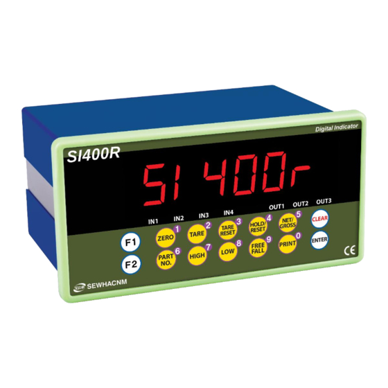
- Page 6 3-2. Front 3-2-1. Display and key pad ① Digital 6 digits ② Unit ③ Condition(Arrow) IN1 : Turn on when INCOM and IN1 are connected IN2 : Turn on when INCOM and IN2 are connected IN3 : Turn on when INCOM and IN3 are connected IN4 : Turn on when INCOM and IN4 are connected OUT1 : Turn on when OUT1(Relay) is connected OUT2 : Turn on when OUT1(Relay) is connected...
- Page 7 3-2-2. Key - Set current weight to Zero (It doesn’t work when hold state or weight is not within near zero range.) - Number 1 - Set TARE - Number 2 - Reset TARE - Number 3 - Hold current weight / RESET - Number 4 - Toggle weight Net/Gross on display - Number 5...
- Page 8 3-2-3. Key combination Double tare setting (To set another tare weight when tare weight is already set.) Print out sub-total Display current weight for 5 seconds Display sub-total weight for 5 seconds Display grand-total weight for 5 seconds Print out the total weight Input tare value by number key (Must set function 530-01.) Delete the sub-total out...
- Page 9 3-3. Real Panel ⑥ ① ② ④ ⑤ ③ ① AC Power input terminal ② Relay out terminal : You can set relay out mode on Function number 141~147. Relay Com terminal is common terminal. ③ External input terminal : zero voltage point (dry contact) ④...
- Page 10 4. Installation 4-1. Size (Unit: mm) 4-2. Panel cutting size (Unit: mm)
- Page 11 4-3. Load cell installation How to connect Load Cell (In case of SEWHACNM’s Load cell) It depends on the manufacturer of load cell, please check the specification. EXC+ White EXC- Green SIG+ Blue SIG- Yellow SHELD 1. When you setup the Load cell, if EXC+ and EXC- have a short circuit, It may cause damage in the indicator.
- Page 12 4-4. Peripheral Equipment 4-4-1. Serial Interface (Basic function) – RS232C and Current loop Equipment INDICATOR 4-4-2. External input (Basic function) – Input 4EA Each output relay function can be changed on Function number 156~159. Connect Input signal to Dry connect. Terminal component - ⅠC : Input common terminal(V+ : 12V DC) - Ⅰ1~Ⅰ4 : Input signal(Output relay: zero voltage point –relay or switch signal)
- Page 13 4-4-3. External input (Basic function) – Output 3EA Each output relay function can be changed on Function number 141~143. Normal open (default), but you can change it to Normal close by changing function 148- 01, 149, 150 and 151. Contact Ratings VDC Contact Ratings VAC 30V 3A 250V 5A...
- Page 14 5. SETUP 5-1. Calibration Calibration is the process of adjusting weight balance between "Real Weight" on the Load Cell and "Displayed weight of Indicator". When you replace Load Cell or Indicator, you have to do Calibration process once again. Before start to the calibration mode, Please turn on the indicator and preheat about 15 min.
- Page 15 STEP 1. Enter the calibration Remove “CAL BOLT” on the rear panel, and press switch inside. When is displayed, press key. When is displayed, press key. STEP 2. Unit setting After is displayed, then unit will be displayed. Press key to select unit kg, g, ton, oz and lb. Press key to save and move to next step.
- Page 16 STEP 4. Decimal point and division setting When shows, Press key to adjust decimal point. Press key to change the decimal point . Press the key to save. - Max decimal point will be 0.001, and the you can change the digit to 1, 2, 5, 10, 20 and 50.
- Page 17 STEP 6. Span calibration When calibration is done, the display shows The maximum weight is shows. Use the number key(0~9), enter the balance weight that already prepared. (※ Balance weight should bigger than 10% of maximum capacity or Er-005 displayed) Press the key.
- Page 18 5-2. Simulation Calibration Mode (Calibrate without Test weight) With this “Simulation Calibration Mode” you can make simple calibration without any “TEST weight” This calibration mode uses “Load cells’ max capacity” and “Max Output Rate(mV)”, so the weight adjustment degree might be less than “Test weight Calibration”. The guaranteed resolution of this “Simulation Calibration”...
- Page 19 STEP 4. Decimal point and division setting When shows Make the decimal point use the key and move the decimal point . Push the key and save it . - Max decimal point will be 0.001, and digit can be selected among 1, 2, 5, 10, 20, 50. Digit and decimal point must be fulfilled under the below condition.
- Page 20 Step 6. Enter the Load cell R/O value(Rated Output Voltage/mV) MODEL: xxxxx display shows. CAPA: 15kg Enter the R/O value in load cell or certification R.O: 1.429mV/V S/N : xxxxxxx key and save the value, the display shows < > Ex) Loadcell label ※...
- Page 21 5-3. Function setting Function setting could set the indicator to operate perfectly with surrounding condition. 5-3-1. Starting F-FUNCTION Mode 1) Press the key 4times for 3seconds. 2) Display shows , press Function number Setting value ※ Function number, Setting value, change the position Select the function number Select the function number and enter the function number to use number key and press the...
- Page 22 5-3-2. F-Function List Subject Default Content Function number 100~119 : Indicator system setting Equipment No. setting (ID 01~99 No.) Weight–back up mode 00 : Normal mode 01 : Weight back up mode(Zero) 02 : Weight back up mode(Zero & Tare) Weighing data save 00 : Manual: Whenever “Print”...
- Page 23 Subject Default Content Function number 120~129 : Print Function Print format setting 00 : Korean 01 : English Paper withdraw rate setting 00 : Continuous print (After continuous/single 01 : Continuous print(Print “Tare”, “Net weight”) print) 02 : Single print 03 : Single print(Print “Tare”, “Net weight”) Paper withdraw rate setting 00 ~ 09 (Unit : 1 line add)
- Page 24 Subject Default Content Function number 140~199 : Digital Input or Out setting External output 00 : Auto setting Auto/Manual 01 : Manual setting External output 1 00 : Disuse 01 : HIGH External output 2 02 : LOW External output 3 03 : Near zero 04 : Finish External output standard...
- Page 25 Subject Default Content Communication speed 00 : 2,400bps 05 : 28,800bps 01 : 4,800bps 06 : 38,400bps 02 : 9,600bps 07 : 57,600bps 03 : 14,400bps 08 : 76,800bps (option) 04 : 19,200bps 09 : 115,200bps Communication mode 00: Simplex / Stream mode 01: Duplex / Command mode 02: Duplex / Command mode (Compatible with SI4000)
- Page 26 Subject Default Content Ethernet transference under 00 : Continuously stream mode 01 : Single time on every steady state (Under F-number 252-00) 02 : Single time at the first steady point 03 : Single time output after HIGH signal 04 : When input Print key Ethernet “Check-Sum”...
- Page 27 Subject Default Content Automatic save data in SD 00 : Disuse memory card 01 : Use...
- Page 28 Subject Default Content Function number 501~599 : Indicator weighing process Weighing mode 00: Disuse 01: Limit mode 1 02: Limit mode 2 03: Limit mode 3 04: Supply mode 00 : Absolute value Relay control type 01 : Positive value Zero relay output absolute value 00 : Near Zero (...
- Page 29 Subject Default Content Tare delay time 00 : Disuse (key input or external input) 01~10 : Use (Unit : 1 second) (Activates after set delay time) Auto zero function under 00 : Disuse tare state 01 : Use Near zero output setting 00 : Zero lamp is on when current value is “0”...
- Page 30 ◆ Weighing mode 1. – Limit mode (Function F500-1) Time Time Contents High Relay out delay time (F510) Function 102-3 or 102-6, after t1, save the weight Set “0”, HIGH value will be out without delay time Relay output Relay Condition Relay Condition...
- Page 31 ◆ Weighing mode 2. – Limit mode (F500-02) Time Time Contents High Relay output delay time (F510) Function 102-3 or 102-6, after t1, save the weight Set “0”, HIGH value will be out without delay time Relay output Relay Condition Relay Condition Current weight <...
- Page 32 ◆ Weighing mode 3. – Limit mode (F500-03) Time Time Contents High Relay output delay time (F 510) Function 102-3 or 102-6, after t1, save the weight Set “0”, HIGH value will be out without delay time Relay output Relay Condition Relay Condition...
- Page 33 ◆ Weighing mode 4. – Supply mode (F500-04) Time Time Contents Finish ouput delay time (F510) If set “0”, Finish signal would be out without delay time. Finish ouput time (F520) If set “F102-3” or “F102-6”, weight value would be saved after t2 Relay Out Relay Condition...
- Page 34 5-3-3. Hidden Function ※ How to enter hidden function mode 1) Press key for 4times, display shows 2) Enter the password that setting on HF06 (Master password: 0060) 3) After is displayed, press key. 4) When shows, press key and user check the hidden function’s contents key is to Increase HF number and key is to Decrease HF number.
- Page 35 Subject Default Remarks HF11 Span value check x.xxxxx cancel key to previous step Use the number key and save HF12 Zero range check and modification 0.000 it to use enter key 00 : Disuse HF13 Simulation calibration Setting 01 : Use Simulated calibration value HF14 Simulated calibration value enter...
- Page 36 Subject Default Remarks HF42 Port Number check and modified 5000 HF43 SERVER IP ADDRESS 1 ~ 4 check and 192.168.0.100 modified HF46 Change value by number key, Communication and press key to save it. 0 : Server mode - Stream mode (F252-00) - Command mode (F252-01) HF47 Sending the date to IP...
- Page 37 5-4. Test mode Disconnected all indicator and equipment when do the test mode. Press key 4times for 3seconds. When display shows , press key.. Display shows , enter the test mode. Enter the various test mode with below key. Test Test How to Checking load cell input...
- Page 38 5-4-2. Deviation of Load cell input value check mode Press the key in the test mode, then displayed actual converted digital value. In this condition, press key then adjusted the digital value as If put some load on the loadcell, loaded value is displayed. This test mode is that check deviation of actual converted digital value.
- Page 39 5-4-4. Display check mode 1) Press key in the test mode, then all display switches on and off. 2) User can check by eyes. 3) Press the key, back to 5-4-5. External input check mode Press key in the test mode, then display If it is shorted between external input terminal I1~I6 and input common terminal IC, it shows which external input is shorted.
- Page 40 5-4-7. Analog output (4~20mA / 0~10V) check mode 1) Press key in to the test mode then display 2) It simulates analog output value from 0(4mV, 0V) to 100(20mV, 10V). 3) If it is selected analog output as 4 ~ 20mA, “A” is shown on the display. Otherwise, “V” is shown on the display under select analog output 0~10V.
- Page 41 6. Option card 6-1. Serial interface 6-1-1. Serial interface OP-01 : RS422 RS422 interface is strong for electrical noise, and it is available for below 1km distance. The RS422 is full-duplex communication, it can connect to external equipment such as PC, PLC, printer or etc with fast speed and multiple use.
- Page 42 6-1-3. Serial interface OP-03 : RS232C RS232C interface is weak for electrical noise, so it is available for below 10meters distance. User can use the RS232C interface to connect with external equipment such as PC, PLC, printer, external display or etc. INDICATOR EQUIPMENT COMPUTER...
- Page 43 6-2. Ethernet interface 6-2-1. Ethernet interface : OP-04 Using Ethernet communication, indicator and other external devices can be communicate. (Communication speed: 10/100Mbps) Function 252-00 (Stream mode) Function 252-01 (Command mode) LINK 10/100 Function 252-03 (Modbus TCP/IP) Mbps 6-3. Analog output 6-3-1.
- Page 44 6-3-2. Analog voltage output interface (0~10V) : OP-06 This output card converts weight value to Analog output signal (0~10V) and transfers to external devices(Recorder, P.L.C), controlled by voltage output. Output voltage 0~10VDC output Accuracy 1/1,000 - Under calibration mode or Ad-Err condition, analog output will not activated. - If the output is deactivated, the last output signal value will be hold until next activation.
- Page 45 6-4. Parallel interface 6-4-1. BCD IN interface (Part number external input card) : OP-07 BCD IN interface is to enter part number of indicator from external equipment such as PC, PLC or ETC. 1) Connector Pin Pin No. Contents Pin No Contents IN 1 IN 2...
- Page 46 6-4-2. BCD OUT interface : OP-08 BCD OUT parallel interface is output current weight in BCD code. This interface can be connected with PC, PL, external display or ETC. 1) Connector pin Pin No. Contents Pin No Contents 1x10 2x10 4x10 8x10 1x10...
- Page 47 6) Signal logic Factory default Contents Remark BDC data Positive Positive Select it by Negative switch which is located on BCD OUT PCB. Polarity When it is “-“, When “-“ is output, open ”H” will be “H” is output output. O.L output When it is “OL”, When it is Over-load, open “H”...
- Page 48 6-5. Data storing device (SD memory card) 6-5-1. Data storing device (SD memory card) : OP-09 SD memory card is a device that saves required weight data according to function 102 setting. SD memory card has to be installed in OP 2 location. 1) Weighing data format (File name: N + Creation date)(ex : N160114) Save weighing data into SD memory card according to function 102 setting.
- Page 49 6-6. Option card combination Maximum 2EA of option card can be installed. Below combination is available. OP-02 OP-05 OP-01 OP-04 OP-07 OP-08 OP-09 OP-03 OP-06 Classification Serial Serial Ether- Analog (RS422, memory (RS232) RS485) card Serial RS232 Serial RS422, RS485 Ethernet Analog out BCD IN...
- Page 50 7. Communication data format 7-1. Simplex (Stream mode) 7-1-1. Format 1 (Excluding ID number) – 18 byte Classification Contents Header1 (2Byte) OL : Current weight is over than max capacity weight. ST : Stable weight US : Unstable weight Header2 (2Byte) NT : NET-WEIGHT(Real weight which is excluded tare weight) GS : GROSS-WEIGHT (Under tare set, it is included real weight and tare weight.)
- Page 51 7-1-2. Format 2 (Including ID number) – 21 byte Classification Contents ID Number (2Byte) ID Number Header1 (2Byte) OL : Current weight is over than max capacity weight. ST : Stable weight US : Unstable weight Header2 (2Byte) NT : NET-WEIGHT(Real weight which is excluded tare weight) GS : GROSS-WEIGHT (Under tare set, it is included real weight and tare weight.) Sign (1Btye)
- Page 52 7-1-3. Format 3 (Including ID number) – 17 byte Classification Contents STX (1Byte) Start of Text ID Number (2Byte) ID Number Header1 (1Byte) OL : Current weight is over than max capacity weight. ST : Stable weight US : Unstable weight Header2 (1Byte) NT : NET-WEIGHT(Real weight which is excluded tare weight) GS : GROSS-WEIGHT...
- Page 53 7-1-4. Format 4 (Including ID number) – 22 byte Classification Contents Header1 (2Byte) OL : Current weight is over than max capacity weight. ST : Stable weight US : Unstable weight Header2 (2Byte) NT : NET-WEIGHT(Real weight which is excluded tare weight) GS : GROSS-WEIGHT (Under tare set, it is included real weight and tare weight) ID Number (1Byte)
- Page 54 7-2. Command mode Under “Command Mode”, Indicator will recognize the receipt of Order based on 02h(STX) and 03h(ETX) signal, and transfers 06h(ACK), 15h(NAK). 7-2-1. Read mode Current weight(Displayed weight) Format : STX(1) ID(2) RCWT(4) ETX(1) Transfer ASCII : STX 01RCWT ETX Byte HEX : 02h 30h 31h 52h 43h 57h 54h 03h Format : STX(1) ID(2) RCWT(4) State1(1) State 2(1) P(1) Decimal point(1)
- Page 55 Sub-total Format : STX(1) ID(2) RSUB(4) ETX(1) Transfer ASCII : STX 01RSUB ETX Byte HEX : 02h 30h 31h 52h 53h 55h 42h 03h Format : STX(1) ID(2) RSUB(4) P(1) Decimal point(1) Part number(2) Sub-total weighing count(6) Sub-total weight(10) Unit(2) ETX(1) Respond ASCII : STX 01RSUBP2010123450123456789kg ETX Byte...
- Page 56 Current date Format : STX(1) ID(2) RDAT(4) ETX(1) Transfer ASCII : STX 01RDAT ETX Byte HEX : 02h 30h 31h 52h 44h 41h 54h 03h Format : STX(1) ID(2) RDAT(4) Current date(6) ETX(1) Respond ASCII : STX 01RDAT171101 ETX Byte HEX : 02h 30h 31h 52h 44h 41h 54h 31h 37h 31h 31h 30h 31h 03h Tare weight Format : STX(1) ID(2) RTAR(4) ETX(1)
- Page 57 SP1 (LOW) Format : STX(1) ID(2) RSP1(4) ETX(1) Transfer ASCII : STX 01RSP1 ETX Byte HEX : 02h 30h 31h 52h 53h 50h 31h 03h Format : STX(1) ID(2) RSP1(4) P(1) Decimal point(1) SP1(6) ETX(1) Respond ASCII : STX 01RSP1P2012345 ETX Byte HEX : 02h 30h 31h 52h 53h 50h 31h 50h 32h 30h 31h 32h 33h 34h 35h 03h SP2 (HIGH)
- Page 58 7-2-2. Write mode Error code 0 : Normality 1 : Check-Sum Error 2 : Received Data length Error 3 : Received Data range Error 4 : Write prohibit error (It is not allowed during run process) Zero set Format : STX(1) ID(2) WZER(4) ETX(1) Transfer ASCII : STX 01WZER ETX Byte...
- Page 59 Hold set Format : STX(1) ID(2) WHOL(4) ETX(1) Transfer ASCII : STX 01WHOL ETX Byte HEX : 02h 30h 31h 57h 48h 4Fh 4Ch 03h Format : STX(1) ID(2) ACK(1) ERROR(1) ETX(1) Normal ASCII : STX 01 ACK 0 ETX HEX : 02h 30h 31h 06h 30h 03h Respond Format : STX(1) ID(2) NAK(1) ERROR(1) ETX(1)
- Page 60 Sub-total print Format : STX(1) ID(2) WSPR(4) ETX(1) Transfer ASCII : STX 01WSPR ETX Byte HEX : 02h 30h 31h 57h 53h 50h 52h 03h Format : STX(1) ID(2) ACK(1) ERROR(1) ETX(1) Normal ASCII : STX 01 ACK 0 ETX HEX : 02h 30h 31h 06h 30h 03h Respond Format : STX(1) ID(2) NAK(1) ERROR(1) ETX(1)
- Page 61 Grand-total delete Format : STX(1) ID(2) WGTC(4) ETX(1) Transfer ASCII : STX 01WGTC ETX Byte HEX : 02h 30h 31h 57h 47h 54h 43h 03h Format : STX(1) ID(2) ACK(1) ERROR(1) ETX(1) Normal ASCII : STX 01 ACK 0 ETX HEX : 02h 30h 31h 06h 30h 03h Respond Format : STX(1) ID(2) NAK(1) ERROR(1) ETX(1)
- Page 62 Part number set Format : STX(1) ID(2) WPNO(4) Part number(2) ETX(1) Transfer ASCII : STX 01WPNO10 ETX Byte HEX : 02h 30h 31h 57h 50h 4Eh 4Fh 31h 30h 03h Format : STX(1) ID(2) ACK(1) ERROR(1) ETX(1) Normal ASCII : STX 01 ACK 0 ETX HEX : 02h 30h 31h 06h 30h 03h Respond Format : STX(1) ID(2) NAK(1) ERROR(1) ETX(1)
- Page 63 SP1, SP2 (LOW, HIGH) Format : STX(1) ID(2) WSPA(4) SP1(6) SP2(6) ETX(1) ASCII : STX 01WSPA012345012345 ETX Transfer HEX : 02h 30h 31h 57h 53h 50h 41h 30h 31h 32h 33h 34h 35h 30h 31h 32h Byte 33h 34h 35h 03h Format : STX(1) ID(2) ACK(1) ERROR(1) ETX(1) Normal ASCII : STX 01 ACK 0 ETX...
- Page 64 7-3. Command mode (SI4010R compatibility mode) 7-3-1. Read Command Current weight(Displayed weight) Format : STX(1) ID(2) RCWT(4) ETX(1) Transfer ASCII : STX 01RCWT ETX Byte HEX : 02h 30h 31h 52h 43h 57h 54h 03h Format : STX(1) ID(2) RCWT(4) State1(2) State2(2) Sign(1) Current weight(7) Unit(2) ETX(1) ASCII : STX 01RCWTST,NT,+0123.45kg ETX Byte...
- Page 65 Sub-total weighing count Format : STX(1) ID(2) RSNO(4) ETX(1) Transfer ASCII : STX 01RSNO ETX Byte HEX : 02h 30h 31h 52h 53h 4Eh 4Fh 03h Format : STX(1) ID(2) RSNO(4) Sub-total weighing count(6) ETX(1) Respond ASCII : STX 01RSNO012345 ETX Byte HEX : 02h 30h 31h 52h 53h 4Eh 4Fh 30h 31h 32h 33h 34h 35h 03h Grand-total...
- Page 66 Tare value Format : STX(1) ID(2) RTAR(4) ETX(1) Transfer ASCII : STX 01RTAR ETX Byte HEX : 02h 30h 31h 52h 54h 41h 52h 03h Format : STX(1) ID(2) RTAR(4) Tare weight(7) ETX(1) ASCII : STX 01RTAR0123.45 ETX Respond Byte HEX : 02h 30h 31h 52h 54h 41h 52h 30h 31h 32h 33h 2Eh 34h 35h 03h Current part number Format : STX(1) ID(2) RPNO(4) ETX(1)
- Page 67 Current weight, INPUT, OUTPUT Format : STX(1) ID(2) RWRS(4) ETX(1) Transfer ASCII : STX 01RWRS ETX Byte HEX : 02h 30h 31h 52h 57h 52h 53h 03h Format : STX(1) ID(2) RWRS(4) Current weight(7/8) External input1~4(4) Relay output1~3(3) ETX(1) Byte Respond ASCII : STX 01RWRS0123450000111 ETX HEX : 02h 30h 31h 52h 57h 52h 53h 30h 31h 32h 33h 34h 35h 30h 30h 30h...
- Page 68 7-3-2. Write command Zero set Format : STX(1) ID(2) WZER(4) ETX(1) Transfer ASCII : STX 01WZER ETX Byte HEX : 02h 30h 31h 57h 5Ah 45h 52h 03h Format : STX(1) ID(2) ACK(1) Format : STX(1) ID(2) NAK(1) ETX(1) ETX(1) Respond Normal Error...
- Page 69 Hold Format : STX(1) ID(2) WHOL(4) ETX(1) Transfer ASCII : STX 01WHOL ETX Byte HEX : 02h 30h 31h 57h 48h 4Fh 4Ch 03h Format : STX(1) ID(2) ACK(1) Format : STX(1) ID(2) NAK(1) ETX(1) ETX(1) Respond Normal Error ASCII : STX 01 ACK ETX ASCII : STX 01 NAK ETX Byte HEX : 02h 30h 31h 06h 03h...
- Page 70 Sub-total delete Format : STX(1) ID(2) WSTC(4) ETX(1) Transfer ASCII : STX 01WSTC ETX Byte HEX : 02h 30h 31h 57h 53h 54h 43h 03h Format STX(1) ID(2) Format STX(1) ID(2) ACK(1) NAK(1) Respond Normal ETX(1) Error ETX(1) Byte ASCII : STX 01 ACK ETX ASCII : STX 01 NAK ETX HEX : 02h 30h 31h 06h 03h HEX : 02h 30h 31h 15h 03h...
- Page 71 Date set Format : STX(1) ID(2) WDAT(4) DATE(6) ETX(1) Transfer ASCII : STX 01WDAT171101 ETX Byte HEX : 02h 30h 31h 57h 44h 41h 54h 31h 37h 31h 31h 30h 31h 03h Format : STX(1) ID(2) ACK(1) Format : STX(1) ID(2) NAK(1) ETX(1) ETX(1) Respond...
- Page 72 <How to calculate CHECK SUM> Sum the value from “STX” to “ETX” and converts to ASCII(2byte) and transfer. Convert the Sum value(HEX) to ASCII and transmit(28byte) . ex) The sum HEX value from STX to ETX(02,30,31,52,43,57,54,03) is 1A6h. Then, divide 1A6h by 100h(1A6h/100h). the rest of result is A6h. Calculated remainder value is A6h, then convert A6h to ASCII, 41(A), 36(6), and transfer...
- Page 73 7-4. Modbus - RO : Read Only - RW : Read Write - Each P/N’s set point can’t over max capacity of Indicator. ex)35.00kg = 3,500 (0xDAC) - When you input date and time, it should be 6digit. ex) 1 January 2014 = 140101 (0x22345) 15(H) : 50(M) : 17(S) = 155017 (0x25D89) - Refer the memory register for regarding Lamp, Error, Digital Input,...
- Page 74 Contents Address Length Feature Part Number 0xC2 Accumulated Weight Part Number 50 Count 0x180 Part Number 50 0x182 Accumulated Weight Date 0x184 Time 0x186 0x188 Part Number 0x18B Current part number 0x18C Current part number 0x18E HIGH Current part number 0x194 HIGH free fall Part number 1 LOW...
- Page 75 7-4-2. External input data map 1bit 2bit 3bit 4bit 5bit 6bit 7bit 8bit IN 1 IN 2 IN 3 IN 4 9bit 10bit 11bit 12bit 13bit 14bit 15bit 16bit 7-4-3. Lamp data map 1bit 2bit 3bit 4bit 5bit 6bit 7bit 8bit Stable Zero...
- Page 76 7-5. Print format It can be connected with all kinds of Serial interface printer, but the print format is already programed and fixed with SE7200/7300 model (30column). So, you can get the right print form by connecting and using that printer. Korean(120-00) English (120-01) Continuous...
- Page 77 Single print (Tare, Net weight) 121-03 Single print (Tare, Gross weight) 121-04 Grand-total Print If it is the first printing in continuous print mode, Date and Time data is like single print mode.
- Page 78 Error & treatment 8-1. Load cell installation error Display Cause Treatment Display 1 The value of input resistance EXC- and 1. Load cell broken 1. Measure input, output EXC+ is 400 2. Load cell insulation resistance of the load cell ±30Ω...
- Page 79 8-2. ERROR code Display Cause Er-001 When Max capacity/digit value is over 20,000 Er-004 Standard weight value is over than Max Capacity Er-005 Standard weight value is less than 10% of Max Capacity Er-006 When Calibration, it is excess than maximum A/D converting value Er-007...
- Page 80 8-3. Error and treatment Below error table show causing of error and treatment, when weighing process is not working or it cannot measure weighing due to indicator error. Display Cause Treatment 1. Under “TEST” mode 1, check analogue value. If you cannot get 1.
- Page 81 Warranty certification This product is passed “SEWHACNM Co., Ltd.’s strict quality test. If there is defect of manufacturing or abnormal detection within warranty period, please contact our Agent or Distributor with this Warranty certificate. Then, we will repair or replace free of charge.
Need help?
Do you have a question about the SI 400R and is the answer not in the manual?
Questions and answers