Table of Contents
Advertisement
Quick Links
Advertisement
Table of Contents

Related Manuals for Sleipner GW-2Y

Summary of Contents for Sleipner GW-2Y
- Page 1 User Manual Including Installation For S-Link Gateway GW-2Y DOCUMENT ID: SLEIPNER GROUP 7807 REVISION: P.O. Box 519 DATE: N-1612 Fredrikstad 2024 Norway LANGUAGE: www.sleipnergroup.com To download your language go to www.sleipnergroup.com...
-
Page 2: Table Of Contents
Typically NMEA2000 Connection Diagram .............................. 8 ® Service and Support ................................. 9 Product Spare Parts and Additional Resources ......................... 9 Warranty Statement ................................. 9 Sleipner Motor AS P.O. Box 519, Arne Svendsensgt. 6-8 N-1612 Fredrikstad, Norway MC_0020 Gateway S-Link 7807... -
Page 3: Introduction
Connection The GW-2Y does not feed any power to the CAN-bus and connected devices has to be power feed from elsewhere. The GW-2Y does not include any termination resistor on the M12 male connector output, so terminating resistors is required on the CAN-bus. CAN-L & CAN-H are galvanic isolated. -
Page 4: Installation Guide
Any attempt to directly control or connect into the S-Link™ control system without a designated and approved interface will render all warranties and responsibilities of all of the connected Sleipner products. If you are interfacing the S-Link™ bus by agreement with Sleipner through a designated Sleipner supplied interface, you are still required to install at least one original Sleipner control panel to enable efficient troubleshooting if necessary. -
Page 5: S-Link Gateway Installation
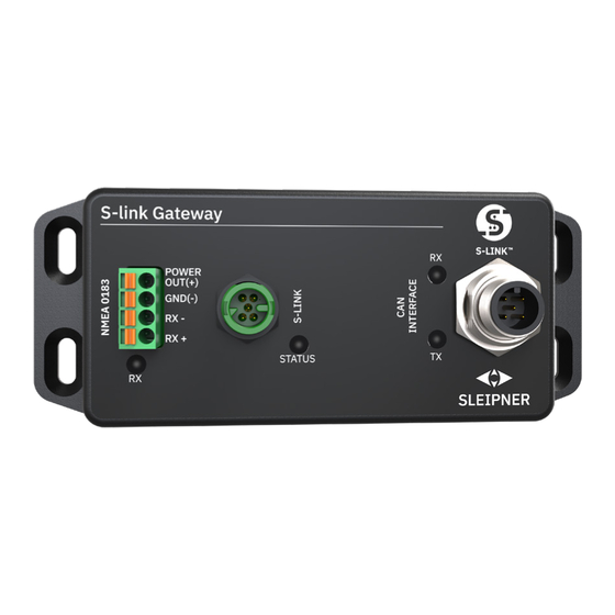
S-Link Gateway Installation MC_0767 Fasten the GW-2Y box to a solid surface using four mounting screws. Attach the required cables to the GW-2Y. MG_0486 NMEA 2000 S-Link NMEA 0183 Gateway S-Link 7807 2024... -
Page 6: Gateway Measurements
GW-2Y Gateway Measurements MC_0762 GW-2Y Measurement Measurement description code mm inch Total Gateway Height Gateway Height 25.5 Gateway Width Total Gateway Length 126.5 Gateway Length MG_0427 Technical Specifi cations MC_0763 Supply Voltage 8-31VDC, Powered from S-Link Power Consumption CAN INTERFACE M12 male connector CAN 2.0B, baud rate 250Kb... -
Page 7: S-Link System Description
MC_0120 S-Link is a CAN-based control system used for communication between Sleipner products installed on a vessel. The system uses BACKBONE Cables as a common power and communication bus with separate SPUR Cables to each connected unit. Only one S-Link POWER cable shall be connected to the BACKBONE Cable. -
Page 8: Typically Nmea2000® Connection Diagram
Typically NMEA2000® Connection Diagram NMEA0183 GPS Antenna Helm Drive ECU System Bus Sleipner System Valve Control GW-2Y etc. Panel Engine Marine Display Gear PPC Unit Thruster motor Joystick Sleipner Panel Engine Marine Display Panel Gear Valve Control Joystick Thruster etc. -
Page 9: Service And Support
11. This warranty gives you specific legal rights, and you may also have other rights which vary from country to country. Patents MC_0024 At Sleipner we continually reinvest to develop and offer the latest technology in marine advancements. To see the many unique designs we have patented visit our website www.sleipnergroup.com/patents Gateway S-Link... - Page 10 © Sleipner Group, All rights reserved The information given in the document was right at the time it was published. However, Sleipner Group cannot accept liability for any inaccuracies or omissions it may contain. Continuous product improvement may change the product specifi cations without notice.
Need help?
Do you have a question about the GW-2Y and is the answer not in the manual?
Questions and answers