Table of Contents
Advertisement
Quick Links
ENG
Hydrosplit-M3
ECCM33 / ECCM33R
Heat/cooling calculator, separated version
USER MANUAL
Premise
The installation must be carried out by qualified personnel only. The manufacturer doesn't assume any
responsibility for improper installation or damages caused by third parties.
Warning
The calculator contains potentially dangerous batteries: handle carefully and do not dump in the
environment.
Hydrosplit M3 user manual - v1.7.1_ENG
1
Advertisement
Table of Contents

Related Manuals for Fantini Cosmi Hydrosplit-M3 ECCM33

Summary of Contents for Fantini Cosmi Hydrosplit-M3 ECCM33
- Page 1 Hydrosplit-M3 ECCM33 / ECCM33R Heat/cooling calculator, separated version USER MANUAL Premise The installation must be carried out by qualified personnel only. The manufacturer doesn’t assume any responsibility for improper installation or damages caused by third parties. Warning The calculator contains potentially dangerous batteries: handle carefully and do not dump in the environment.
-
Page 2: Package Contents
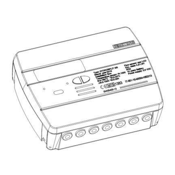
INTRODUCTION The model Hydrosplit-M3 is a separate electronic calculator that measures the thermal energy used in the heating and cooling systems. The calculator allows the simultaneous calculation of: - Thermal energy in a heating/cooling system. - Volume up to 2 flow meters for hot and cold sanitary water. The calculator is equipped with two pulse emitter outputs (one for the heating data and one for the cooling data) and one output for the Wired M-Bus network link. -
Page 3: Installation
INSTALLATION CALCULATION UNIT Open the calculation unit by leveraging on the four hooks on the sides [1] and remove the cover [2]. Remove the bracket behind of the calculation unit and secure it to the wall. There are two types of wall mounting allowed: direct wall mounting by using the mounting bracket and the following hooking of the calculation unit on the same bracket;... -
Page 4: Components Connections
Then apply the basis on the bracket and secure it with any anti-removal seals. After the installation, connection, configuration and commissioning, close the cover and apply adhesives and / or lead sealings. TEMPERATURE SENSORS INSTALLATION For the temperature sensors installation, see related manual. FLOW METERS INSTALLATION For the flow meters installation, see related manual. -
Page 5: Temperature Sensors Connection
TERMINAL BOARD DESCRIPTION Numbers Indication Description Inlet temperature sensor 1/5/6/2 Forward flow return temperature sensor 3/7/8/4 Return flow Flow meter input 10/11/50 Flow IN Volume meter input 1 51/52/53 C1 IN Volume meter input 1 54/55/56 C2 IN Cooling pulse output 57/58 Cold OUT Heating pulse output... -
Page 6: Flow Meter Connection
Connect the inlet temperature sensor in the terminals 5 and 6; Connect the return temperature sensor in the terminals 7 and 8; Warning: To avoid errors in the energy calculation, respect the correspondence between the inlet andreturn temperature sensors and the respective terminals. Use PT1000 temperature sensors only, EN1434- 2 MID (2004/22/CE) approved. -
Page 7: Pulse Output Connections
VOLUME METERS C1/C2IN CONNECTION The inputs C1 IN (51, 52, 53) and C2 IN (54, 55, 56) are dedicated to the flowmeters for hot and cold sanitary water. The calculation unit is compatible with flowmeters with pulse output OC (open collector) or OA (reed), with pulse value “liters/pulse”... - Page 8 M-BUS NETWORK CONNECTION The inputs/outputs “M-Bus” (24 and 25) are dedicated to the calculator connection with an M-Bus network cable. For the connection is not necessary to respect the polarity, although it is advisable to keep the same polarity on the entire cable network. Warning: the M-Bus network is using voltage that can damage the device when applied to terminals dedicated to other functions, so be careful when connecting to this interface.
- Page 9 AUX POWER SUPPLY CONNECTION The terminals 59 and 60 (Aux Power) are dedicated to the connection of the calculation unit to an external electric network by using a power adapter (3.6 ÷ 5 VDC, 300 mA) provided as an accessory. When connected to the power supply, the battery will be used as backup power source.
-
Page 10: Communication Interfaces
COMMUNICATION INTERFACES HEATING/COOLING PULSE OUTPUT INTERFACE The pulse outputs (Open Collector – max. 30V, 50mA), when connected to suitable totalizers compatible, allow the remote reading of heating and refrigeration units consumption. The calculation unit is equipped with a pulse output dedicated for heating units (16, 17) and one dedicated to the refrigeration units (57, 58). -
Page 11: Display And Buttons
DISPLAY AND BUTTONS The calculator is equipped in the front with a liquid crystal display and two buttons (T1 and T2), useful for the configuration of the parameters and for the readings. 1) Eight-digit numeric field; 2) Single-digit numeric index (menu level); 3) Heating data index;... -
Page 12: Programming Menu
6) Return flow temperature index; 7) Inlet flow temperature index; 8) Battery level indicator; 9) Faults indicator; 10) Heating system flowmeter index; 11) Wired M-Bus data index; 11+12) Wireless M-Bus data index (predisposition); 13) Historical data index; 14) Pulse value index (k); 15) Measurement unit index;... - Page 13 The value can be selected by using the button T1: 0.1–0.25–1–2.5–10–25–100–250 L/imp Confirm the selected parameter by holding the T2 button for more than 3 seconds, thus moving to the next parameter. Warning: the pulse value “k” of the heating system flowmeter is settable only once. Once the configuration is confirmed, this parameter is no longer editable.
- Page 14 5) The fifth parameter that has be configured is the enabling/disabling of the anti-tampering contact of the C1 cold/hot water meter. By using the T1 button, proceed with the enabling [1] or disabling [0]. Confirm the selected parameter by holding the T2 button for more than 3 seconds, thus moving to the next parameter.
- Page 15 Confirm the selected parameter by holding the T2 button for more than 3 seconds, thus moving to the next parameter. 10) The tenth parameter that has be configured is the pulse value "k" of the OC pulse cooling output (cold out).
- Page 16 14) The fourteenth parameter that has be configured is the primary address of the Wired M-Bus (M-Bus) of the cooling data. Select the digit using the T2 button and change the single numbers with the T1 button. Confirm the selected parameter by holding the T2 button for more than 3 seconds, thus moving to the next parameter.
- Page 17 1.3 Display test – All segments off 1.4 Accounted energy (cooling) – cumulative value 1.5 Volume useful for the accounting (heating) – cumulative value 1.6 Volume useful for the accounting (cooling) – cumulative value 1.7 Total volume (first pulse input - C1) – cumulative value (optional) 1.8 Total volume (second pulse input –...
- Page 18 2.5 Temperature difference LEVEL 3: SETTINGS (DISPLAYING ONLY) 3.1 Serial number 3.2 Firmware version 3.3 Communication Firmware version 3.4 Current Date 3.5 Liters/pulse value for input flow sensor (flow in) 3.6 Measurement unit (0= Mwh, 1= GJ) 3.7 Input flow sensor (Flow in) anti-tampering activated/deactivated 3.8 Liters/pulse value for first input flow meter (C1)
- Page 19 3.11 Liters/pulse value for second input flow meter (C2) 3.12 Starting value second input flow meter (C2) 3.13 Input flow meter (C2) anti-tampering activated/deactivated 3.14 Liters/pulse value for heating pulse output (Hot out) 3.15 Liters/pulse value for cooling pulse output (Cold out) 3.16 M-Bus Secondary address (Heating) 3.17 M-Bus Primary address (Heating)
- Page 20 LEVEL 3: SETTINGS (CONFIGURATION) The setting of the parameters can be enabled by pressing T2 for 3 seconds while viewing one of the points of the level 3. 3s.1 Password request to enable parameters setting 3s.2 Liters/pulse value setting for input flow sensor (flow in) 3s.3 Input flow sensor (Flow in) anti-tampering activated/deactivated setting...
- Page 21 3s.11 Liters/pulse value for cooling pulse output (Cold out) 3s.12 M-Bus Secondary address setting (Heating) 3s.13 M-Bus Primary address setting (Heating) 3s.14 M-Bus Secondary address setting (Cooling) 3s.15 M-Bus Primary address setting (Cooling) 3s.16 Saving parameters settings and exit 1 = save and exit, 0 = don’t exit Hydrosplit M3 User manual - v1.7.1_ENG...
- Page 22 LEVEL 4: MEMORY DAY DATA 4.1 Memory Day 4.2 Accounted Energy (heating) – cumulative value at memory day 4.3 Accounted Energy (cooling) – cumulative value at memory day 4.4 Accounted Volume (C1) – accounted volume at memory day (optional) 4.5 Accounted Volume (C2) – accounted volume at memory day (optional) Memory day setting: View any of the points in the level 4...
- Page 23 5.3 Historical data storage (up to 26 possible values, saving at the end of the month) 5.3.1 Accounted Energy (heating) – cumulative value at historical memory day 5.3.2 Accounted Energy (cooling) – cumulative value at historical memory day 5.3.3 Accounted Volume (C1) – accounted volume at historical memory day (optional) 5.3.4 Accounted Volume (C2) –...
-
Page 24: Errors And Faults
COMMISSIONING Premise: the procedures explained in this paragraph must be carried out only after the conclusion of the installation phases, the connection procedures and after the testing of the hot/cold water and heating/cooling systems. Warning: once the calculation unit has accounted energy and volumes, some of the settable parameters will no longer be editable. - Page 25 Here is a list of all the error codes: Error Description Prescription Notes One of the two temperature sensor Check the integrity and the The alarm automatically Err101 cables is cut; connection of the temperature resets when the issue is At least one cable is disconnected sensor cables.
- Page 26 BATTERY AND REPLACEMENT PROCEDURES The calculation unit constantly checks the battery status (average lifetime: 10 years) and signals the imminent discharge showing the icon on the display. The signal will be shown one year before the complete discharge. For the replacement, contact the manufacturer. Warning: the calculation unit is equipped with non-rechargeable batteries, that can be dangerous when used improperly.
- Page 27 CALCULATION UNIT DATA SHEET Model Hydrosplit M3 Power supply -Battery supply -Electrical supply (optional, 3.6 ÷ 5 VDC, 300 mA): in this case, the battery will be used as backup power supply) Battery type Li-SoCl2 Lithium-thionyl chloride, 3,6V “size D” 20Ah Battery Life 10 years +1 Operating temperature range...
- Page 28 Operative counting conditions Heating: ΔΘ≥1K and fluid temperature ≥5°C (accounting enabling conditions) Cooling: ΔΘ≥0.2K and fluid temperature ≤24°C Maximum measurable power 99 MW Maximum measurable flowrate 2000 m3\h Display LCD, 8 digits + icons Measurement unit MWh (standard), GJ (optional) Temperature sensors Pt1000 (two-wired) Cable length...
- Page 29 FUNCTIONING BEYOND THE LIMITATIONS DECLARED It is recommended to ensure that the measurement conditions are within the exposed limits of certification. The unit doesn’t disable the functioning outside these ranges, its use is not covered by the certification if the measurement conditions don’t meet the certification validity conditions. Regarding the flow measurement conditions of the flow sensor connected to the calculator, always respect of the flow rates recommended in the table here below depending on the factor of the flow sensor.
-
Page 32: Supporto Tecnico
FANTINI COSMI S.p.A. Via dell’Osio, 6 - 20049 Caleppio di Settala, Milano - ITALY Tel. +39 02 956821 - info@fantinicosmi.it www.fantinicosmi.it SUPPORTO TECNICO supportotecnico@fantinicosmi.it EXPORT DEPARTMENT export@fantinicosmi.it...
Need help?
Do you have a question about the Hydrosplit-M3 ECCM33 and is the answer not in the manual?
Questions and answers