Table of Contents
Advertisement
Quick Links
Advertisement
Table of Contents

Related Manuals for Cromtech Outback CTG2500iP Platinum


Summary of Contents for Cromtech Outback CTG2500iP Platinum
- Page 1 OWNER’S MANUAL CTG2500iP Platinum Portable Petrol Inverter Generator...
- Page 2 Thank you for purchasing your Cromtech Outback™ 2.4kVA portable petrol inverter generator. This manual provides an understanding of the operation and maintenance of this generator. Please read this manual carefully before operating the machine. For any questions regarding operation or maintenance, please consult your local service agent.
-
Page 3: Table Of Contents
Index Warranty......................S Consumer Advice ................Crommelins Machinery: ..............Location Of Important Labels ............... 6 Symbol Meanings ................Safety lnformation.................... 8 Highly Flammable Poisonous Fuel..........Hot Engine Muffler ..............Electric Shock Prevention..............10 Connection Notes ................11 CTG2500iP Diagram .................. 12 Control Panel .................. - Page 4 Carburetor Adjustment ..............Spark Plug Inspection ..............Engine Replacement..............Flame Retardant Element And Screen ......... 28 Filter Replacement..............29 Fuel Tank Filter ................30 Troubleshooting................... 30 Engine Will Start ..............30 Generator Has No Output.............. 31 Storage......................Drain The Fuel ................Protect The Engine ................
-
Page 5: Warranty
WARRANTY CROMTECH™ and CROMTECH OUTBACK™ are a registered trademark of Crommelins Machinery. Crommelins Machinery warrants their goods against defects in materials and workmanship under normal use and service. The Crommelins Machinery warranty does not cover fair wear commensurate with the age of the product, any damage caused by accident, abuse, misuse, neglect, or failure to observe proper operating instructions or proper machinery maintenance as described in the instruction manual. -
Page 6: Location Of Important Labels
LOCATION OF IMPORTANT LABELS NOTE: Maintain/replace safety and instruction labels, if worn or illegible when necessary. CTG2500iP Series - Safety and instruction labels ① ② ③ ④ Pg. 6... -
Page 7: Symbol Meanings
SYMBOL MEANINGS (Refer to SAFETY INFORMATION for more details. Page 8) Attention! Become alert! Your safety is important! Read the manual before operation. Be careful of poisonous exhaust. Never operate the machine in a closed area. Avoid touching hot surfaces, such as engine and muffler. -
Page 8: Safety Lnformation
SAFETY INFORMATION Do not use in a closed vehicle This generator is not designed for marine use. Do not modify or use the generator with any component removed. Do not allow children to use the generator. Make sure to move the generator only with the carry handle. -
Page 9: Highly Flammable Poisonous Fuel
HIGHLY FLAMMABLE AND POISONOUS FUEL Always stop the engine when refueling. Do not operate, refuel, or store generator near any source of ignition, including fire, heater, grinding sparks etc. Never refuel when smoking or near an open flame. Be careful not to spill any fuel on the Engine or muffler when refueling. -
Page 10: Electric Shock Prevention
Do not operate the generator in a confined space or when covered with dust cover (or other materials). Ensure the engine and muffler are completely cooled, before covering generator. ELECTRIC SHOCK PREVENTION Never operate generator in rain or snow to avoid electric shock. -
Page 11: Connection Notes
CONNECTION NOTES DO NOT connect the generator to commercial power sockets. DO NOT connect the generator in parallel with any other generator. ① Correct ② Incorrect WARNING: Before connecting the generator to a building’s electrical system, a licensed electrician must install an isolation (transfer) switch to main fuse box. -
Page 12: Ctg2500Ip Diagram
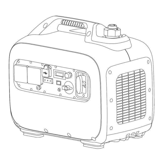
CTG2500iP DIAGRAM ① Vent knob ② Fuel tank cap ③ Fuel tank ④ Handle ⑤ Recoil starter handlebar ⑥ Choke cable ⑦ Control panel ⑧ Muffler ⑨ Main switch ⑩ Engine oil cover (plug) ⑪ Drain screw, carburetor ⑫ Air filter cover ⑬... -
Page 13: Smart-Throttle Switch (Eco-Mode)
SMART-THROTTLE SWITCH (ECO-MODE) ① ON - When smart-throttle switch is in ON position, the economic control mode will automatically adjust the engine speed according to the connected load, so as to achieve low fuel consumption and low noise. ② OFF - When smart-throttle switch is in the OFF position, the engine will run at rated speed (5000rpm), regardless of load. -
Page 14: Low Oil Alarm (Yellow)
LOW OIL ALARM (YELLOW) If the engine oil level falls below the lower level, the low oil alarm will turn on, and the engine will stop automatically. Refill engine oil, otherwise, engine will not start. ① Engine Oil Alarm NOTE: If the engine won’t start, turn the main switch to ON position, then pull the recoil starter. - Page 15 3. Check for blockages around cooling air inlet and control unit. If blocked, clear it 4. Restart the engine after checking NOTE: The generator output automatically resets when engine is stopped and then restarted. NOTE: The overload indicator light may be ON for a few seconds at first when using electric devices that require a large starting current, such as air conditioner, air compressor, submersible pump, or high-power DC...
-
Page 16: Output Indicator (Green)
OUTPUT INDICATOR (GREEN) When the engine is started the output indicator turns ON (Green). ① Output indicator FUEL TANK CAP VENT KNOB The fuel tank cap has a vent to balance inner and outer pressure of fuel tank and stop fuel flow. Turn the vent knob clockwise from OFF to ON to allow fuel to flow into carburetor to allow the generator to start. -
Page 17: Pre-Operation Check
PRE-OPERATION CHECK NOTE: Pre-operation checks should be made each time before using the generator. FUEL Open fuel tank cap, fill with unleaded fuel to red mark inside fuel filling screen. The recommended fuel is unleaded gasoline #93 octane or above. NOTICE: If there is any spilled fuel, use a clean and dry soft cotton cloth to wipe... -
Page 18: Engine Oil
ENGINE OIL Check the oil level by placing generator on a level surface and inspecting at the oil filter hole. The oil should be level with the Lower edge. Add oil if necessary. ① Lower edge, oil filter hole NOTICE: The generator leaves the factory without engine oil. -
Page 19: Operation Instructions
OPERATION INSTRUCTIONS WARNING: Always operate generator in a well- ventilated area. Never operate generator in a closed in area as it may cause unconsciousness or even death within minutes. NOTE: Clean dust, dirt, or water off the socket before use. Before starting the engine, do not connect any electrical devices. - Page 20 2. Turn the main switch to ON position. This turns on the Ignition circuit and allows the fuel to flow. 3. Pull out choke cable button completely. ① Choke cable button NOTE: Choke is not required when starting a warm engine. Set choke back to original position.
-
Page 21: Application Range
APPLICATION RANGE When using the generator, please make sure the total load is under the range of generator rated output, or the generator may be damaged. NOTE: The overload alarm indicator ① is on (red) When total watts exceed the application range. (See page 14 for more details.) CTG2500iP Power Factor... -
Page 22: Ac Connection (Powering Equipment)
AC CONNECTION (POWERING EQUIPMENT) WARNING: Be sure all electric devices are turned off before connection. NOTICE 1. Be sure all electric devices including lines and plugs connections are in good condition before connecting to generator. 2. Be sure the total load is within generator rated output. -
Page 23: Usb Charging Connection
USB CHARGING CONNECTION NOTICE Open USB Cover for Make sure it is the correct direction when inserting into the generator. Change the direction Pg. 23... -
Page 24: Stopping The Engine
STOPPING THE ENGINE NOTE: Disconnect all electric devices. Place smart-throttle switch in position of OFF. 1. Disconnect all electric devices. 2. Turn the main switch to OFF position. 3. Turn the vent knob to OFF position to close vent hole (when engine is completely cooled down). -
Page 25: Maintenance
MAINTENANCE It is an owner’s requirement to periodically inspect, adjust, lubricate and maintain their generator to keep it in good working condition. NOTE: Use only genuine parts for replacement, contact Crommelins spare parts 1300 554 524. WARNING: Consult your local service agent for all major maintenance work. -
Page 26: Carburetor Adjustment
CARBURETOR ADJUSTMENT Consult your local service agent for any adjustments on the carburetor as special equipment is required for correct adjustment. SPARK PLUG INSPECTION 1. Remove spark plug cover and spark plug cap. ① Spark plug cover ② Spark plug cap 2. -
Page 27: Engine Oil Replacement
ENGINE OIL REPLACEMENT WARNING: Never drain engine oil immediately after turning off engine. Let the engine cool first to avoid scalding. 1. Place generator on a level surface and start engine for few minutes to reduce the engine oil viscosity. Shut-off the engine and turn the fuel tank cap vent knob to OFF. -
Page 28: Flame Retardant Element And Screen
FLAME RETARDANT ELEMENT AND SCREEN WARNING: Engine and muffler become very hot when running. Avoid touching the engine and muffler and ensure engine and muffler have cooled before inspecting element and screen. 1. Remove screws on both sides, and disassemble exhaust cover. ①... -
Page 29: Air Filter Replacement
AIR FILTER REPLACEMENT 1. Loosen screws and remove air intake cover. ① Screw ② Air intake cover 2. Loosen screw, remove air filter cover, and take out filter element. ③ Screw ④ Air filter cover ⑤ Filter element 3. Wash the filter element in solvent and dry it. -
Page 30: Fuel Tank Filter
FUEL TANK FILTER 1. Open fuel tank cap and take out inlet filter screen. Remove fuel outlet line and take out fuel outlet filter screen. ① Fuel tank cap ② Fuel filling filter screen ③ Fuel outlet pipe, fuel tank ④... -
Page 31: Generator Has No Output
2. Low engine oil level: • Add engine oil to specified position. 3. Electrical system • Check main switch, and turn it to position ON. 4. Poor spark • Spark plug is dirty with carbon or wet: Remove carbon or wipe and dry spark plug. -
Page 32: Storage
STORAGE For long term storage of your machine, follow these preventive procedures to guard against deterioration. DRAIN THE FUEL 1. Remove fuel tank cap. Drain the fuel from fuel tank into an approved gasoline container by a commercially available hand siphon. Then install the fuel tank cap. 2. -
Page 33: Clean The Generator
CLEAN THE GENERATOR 1. Clean the exterior part of the generator. Use only damp cloth with mild detergent. Avoid excess moisture. 2. Store the generator in a dry and well-ventilated place, with a clean cloth covered. 3. The generator must remain in a vertical position when stored, carried, and operated. -
Page 34: Wiring Diagram
WIRING DIAGRAM Pg. 34... -
Page 35: Ctg2500Ip Specifications
CTG2500iP SPECIFICATIONS 2.4kVA CROMTECH™ GENERATOR 2400watts Max. Wattage 2100watts Cont. Wattage Type Single Phase Power Factor Voltage Regulation Inverter / Pure Sine Wave 2.5% THD AC Output 230V - 50hz Cromtech Engine LH148F(G) 4 stroke, air-cooled, single cylinder, OHV Engine Type gasoline engine Displacement 2.6kw, 79cc... -
Page 36: Standard Features
WIRING DIAGRAM STANDARD FEATURES • Outlets (single phase - 15 Amp) x2 • USB Charging (5V-2 Amp) x2 • Pure Sine Wave <2.5% THD suits precise instruments • Super quiet running at 52-59dbs • Low oil alarm, overload alarm, output indicator •... - Page 40 CROMTECH OUTBACK™ is a registered trademark of Crommelins Operations Pty Ltd, ABN 11 008 889 656...
Need help?
Do you have a question about the CTG2500iP Platinum and is the answer not in the manual?
Questions and answers