Table of Contents
Advertisement
Quick Links
STP Series Turbomolecular Pumps
D
Read through the Safety Precautions and each section of this
Manual carefully before using the STP pump.
Keep this Manual in a place where you can quickly access it
at any time.
Read this Manual thoroughly and keep it with the
Turbomolecular Pump Instruction Manual.
Instruction Manual
Display Unit iDT-002
Copyright 2023 Edwards Japan Limited. All rights reserved. Printed in Japan.
Applicable Models:
◼ STP-iXA2206 series
◼ STP-iXA3306 series
◼ STP-iXA4506 series
◼ STP-iX3006 series
◼ STP-iX457 / iXU457 series
◼ STP-iS1607 series
◼ STP-iS2207 series
◼ STP-iXA3307 series
◼ STP-iXA4507 series
Edwards Japan Limited. All rights reserved. Printed in Japan.
MT-91E-A01-B
2023.08
Advertisement
Table of Contents

Subscribe to Our Youtube Channel
Related Manuals for Edwards iDT-002


Summary of Contents for Edwards iDT-002
- Page 1 Keep this Manual in a place where you can quickly access it at any time. Read this Manual thoroughly and keep it with the Turbomolecular Pump Instruction Manual. 2023.08 Copyright 2023 Edwards Japan Limited. All rights reserved. Printed in Japan. Edwards Japan Limited. All rights reserved. Printed in Japan.
- Page 2 This page is intentionally blank.
-
Page 3: Table Of Contents
Scope and definitions Limited warranty 1.2.1 Item warranted 1.2.2 Disclaimer TECHNICAL DATA Display unit iDT-002 specifications INSTALLATION OF THE DISPLAY UNIT IDT-002 Unpackaging Connectable display unit iDT-002 Front panel Side panel and rear panel Precautions before installation 3.5.1 Operating environment Installation 3.6.1... - Page 4 Input operation port set mode 4.9.1 Input operation port setting 4.9.2 Setting procedure TROUBLESHOOTING Specific error messages of the display unit iDT-002 "FAILURE" LED illuminates or "w" is displayed in the upper left-hand corner of the LCD Cleaning Transport for repair or overhaul STP-LINK...
- Page 5 Display Unit iDT-002 CONTENTS (CONTINUED) PAGE Section Title Page SERVICE, SPARES, AND ACCESSORIES Introduction Service Spares Accessories MT-91E-A01-B Page iii...
- Page 6 Display Unit iDT-002 ILLUSTRATIONS PAGE Figure Title Page Display unit iDT-002 dimensions Front panel Side panel and rear panel Connecting to the STP pump (STP-iS1607/iS2207 series) Connecting to the STP pump (STP-iXA2206/iXA3306/iXA4506/iX3006 series) Connecting to the STP pump (STP-iXA3307/iXA4507 series) 13...
- Page 7 Display Unit iDT-002 TABLES PAGE Table Title Page iDT-002 front panel function iDT-002 front panel function (continued) iDT-002 X3 Connector pin layout Setting for “PORT SELECT IN” input iDT-002 operation mode LCD line Confirmation Mode items (1/2) Confirmation Mode items (2/2)
- Page 8 Display Unit iDT-002 PAGE This page is intentionally blank. MT-91E-A01-B Page vi...
-
Page 9: Introduction
This manual provides installations, operations, and maintenance instructions for the display unit iDT- 002. Use the display unit iDT-002 as specified in this manual. Install, operate, and maintain the display unit followed by this manual. Important safety information is highlighted as WARNING and CAUTION instructions;... -
Page 10: Limited Warranty
1. This warranty applies only to the product delivered from Edwards to the customer. 2. If any defect is found during this period, Edwards will, at its option, repair or recondition the product free of charge. The costs for repair or replacement of the product after the warranty period has passed will be at your own charge. -
Page 11: Technical Data
(2 lines of 16 characters) Input/Output terminal (5 pins) (6 pins) (Option) For direct connection of iDT-002 to STP- iX457/iXU457 (9 pins) STP-Link (8 pins) *1 A version with X3 connectors can also be available. Contact Edwards for further information. MT-91E-A01-B Page 3... -
Page 12: Display Unit Idt-002 Dimensions
Display Unit iDT-002 (A) Without X3 connecter (B) With X3 connecter Figure 1 - Display unit iDT-002 dimensions MT-91E-A01-B Page 4... -
Page 13: Installation Of The Display Unit Idt-002
INSTALLATION OF THE DISPLAY UNIT iDT-002 CAUTION DO NOT use the display unit iDT-002 for different purposes. The display unit iDT-002 is designed to operate and provide a status indication of the STP turbomolecular pump. Use the display unit only for the pump models specified in this manual. -
Page 14: Front Panel
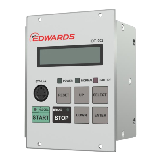
Display Unit iDT-002 Front panel LCD panel UP switch STP-Link connector DOWN switch ACCEL. LED ENTER switch BRAKE LED SELECT switch START switch 10 POWER LED STOP switch NORMAL LED RESET switch FAILURE LED 11 Bracket Figure 2 - Front panel Note: Refer to Table 1 and Table 2 for front panel functions. -
Page 15: Idt-002 Front Panel Function
(Press the "DOWN" and "SELECT" switches simultaneously to enter Manual Operation Mode.) Input operation port setting mode change function (Press the "ENTER" and "SELECT" switches simultaneously to enter Input Operation Port Setting Mode.) Table 1 - iDT-002 front panel function MT-91E-A01-B Page 7... -
Page 16: Idt-002 Front Panel Function (Continued)
STP pump. The LCD has an error message simultaneously. Bracket This is for fixing the display unit iDT-002 to a rack. Refer to Section 3.7, "Attaching the display unit to a rack”. Table 2 - iDT-002 front panel function (continued) -
Page 17: Side Panel And Rear Panel
Connector for iDT-002 harness X3 connector For direct connection of iDT-002 to STP- (Option) iX457/iXU457 *1 A version with X3 connectors can also be available. Contact Edwards for further information. Figure 3 - Side panel and rear panel MT-91E-A01-B Page 9... -
Page 18: Precautions Before Installation
Display Unit iDT-002 Precautions before installation 3.5.1 Operating environment Install the display unit iDT-002 in a place meeting the following requirements: Ambient Temperature 0 to 40 ºC Ambient Relative Humidity 30 to 95 % (non condensing) ⚫ Environment A place at an altitude of 2,000 m or less ⚫... -
Page 19: Installation
CAUTION Ensure a communication cable has been locked securely when using the display unit iDT-002 that does not fix any places. CAUTION Use the communication cables that we have specified when communicating with STP pumps. -
Page 20: Connecting To The Stp Pump
Connecting to the STP pump Connect a display unit iDT-002 to the X5 STP-LINK connector of an STP pump with a communication cable. The STP pump in Figure 4 and Figure 6 is a typical pump model. Refer to the STP pump Instruction Manual for the configuration of each STP pump. -
Page 21: Connecting To The Stp Pump (Stp-Ixa3307/Ixa4507 Series)
CAUTION The connector for a communication cable (refer to Figure 7) on a Display unit iDT-002 is not waterproof and dust-proof. DO NOT leave a Display unit iDT-002 connected to a pump in an environment affected by dust and water splashes. -
Page 22: Communication Cable
Display Unit iDT-002 Installation: 1. Connect CN1 of the communication cable to the X1 connector of the display unit iDT-002, and secure it with the screw (see Figure 7). The recommended tightening torque of the CN1 fixing screw is 0.40 to 0.45 Nm. -
Page 23: Stp-Ix457/Ixu457 Series (Using The Power Supply Unit Ipd-240-24V)
Display Unit iDT-002 3.6.2 STP-iX457/iXU457 series (using the power supply unit iPD-240-24V) When purchasing the power supply unit iPD-240-24V with STP-iX457/iXU457 series pump, the display unit is delivered attaching to the power supply unit. Power supply unit iPD-240-24V STP pump... -
Page 24: Stp-Ix457/Ixu457 Series (Not Using The Power Supply Unit Ipd-240-24V)
3.6.3 STP-iX457/iXU457 series (not using the power supply unit iPD-240-24V) The iDT-002 display unit with X3 connector can be used to connect the iDT-002 to the STP pump STP-iX457/iXU457 series without using the iPD-240-24V power supply unit. Connect the X3 connector of the iDT-002 to the X1 connector of the STP pump. -
Page 25: Attaching The Display Unit To A Rack
Therefore, this panel can be attached to the commercially available racks designed with EIA standards. Installation: Attach the display unit iDT-002 front panel to a rack using the screw holes for the front panel. Note: For the dimensions of the front panel, see Figure 2. - Page 26 Display Unit iDT-002 This page is intentionally blank. MT-91E-A01-B Page 18...
-
Page 27: Operation
LCD indication in power ON state When a display unit iDT-002 is powered ON, the model and version of the display unit are displayed on the LCD. After a few seconds, the display unit iDT-002 displays the pump operation state and allows it to be controlled. -
Page 28: Power Off
• Power Off an STP pump while connecting a communication cable to the STP-LINK connector on the display unit iDT-002, then iDT-002 is also to be powered off automatically. • While the STP pump is in a power-on state, disconnect the communication cable from the STP- LINK connector, then the display unit iDT-002 is to be powered off automatically. -
Page 29: Stp Pump Starting Operation
In this case, "Invalid RESET" is displayed for approximately 2 seconds. Note: When a display unit iDT-002 detects a communication error, the operation of the STP pump is invalid. MT-91E-A01-B... -
Page 30: Operation Mode Of Display Unit
Display Unit iDT-002 Operation mode of display unit The display unit iDT-002 has five operation modes as shown in Table 5 . Any operation modes are effective to operate the STP pump at in every port regardless of the input operation port setting. -
Page 31: Operation Mode
Display Unit iDT-002 Operation mode The operation mode provides the operation state, warning, and failure detection. The operation mode is displayed on the LCD after powering ON the display unit iDT-002. 4.5.1 Operation state STP pump state is displayed on the upper line of the LCD. -
Page 32: Error Contents
Display Unit iDT-002 4.5.2 Error contents If an abnormality/error is detected, "Err No.**/**" and the error message contents are displayed alternately on the lower line of the LCD. The "**/**" part of the "Err No.**/**" shows "error No. / total number of errors". Thus, a "1/3" would denote the earliest error of three errors. -
Page 33: Warning Contents
Display Unit iDT-002 4.5.3 Warning contents When the STP pump detects a warning, a "w" mark appears in the upper left-hand corner of the LCD. When a "w" is displayed, press the "ENTER" switch to display the warning message. When the LCD displays the warning message, the display will automatically return to the pump operation state if any switches are not pressed for two seconds. -
Page 34: Confirmation Mode
Display Unit iDT-002 Confirmation mode The confirmation Mode allows checking the following items of the STP pump. The available item groups 1 through 5 in Table 7 and Table 8 are displayed in order. The active functions is depending on the STP pump models. The unavailable items are displayed as "Unsupported”. -
Page 35: Confirmation Mode Items (2/2)
Display Unit iDT-002 STP pump model iXA2206 Group Item iX457 iS1607 iXA3306 iXA3307 iXU457 iS2207 iXA4506 iXA4507 series series iX3006 series series Available Available Available Available Function Input operation port setting NOT available Available Available Available setting TMS function setting... -
Page 36: Operation Method
Display Unit iDT-002 4.6.1 Operation method Refer to Figure 14 and Figure 15. 1. Press the "SELECT" switch to enter the “Confirmation Mode” while the “Operation Mode” is displayed. 2. Press the "UP" switch to display the next menu in the same group. Press the "DOWN" switch to display the previous item in the same group. -
Page 37: Confirmation Mode Operation Method (1/2)
Display Unit iDT-002 Levitation NORM :*****rpm ・・・・・ SELECT Pump Type Software Version Driver Version AMB Version STP-xxxxx xx_x x.x MD x.x DP x.x DOWN AMB Prm Version MP x.x SELECT Pump Serial No. Date Time Pump Hour Countr Ctrl Hour Countr... -
Page 38: Confirmation Mode Operation Method (2/2)
Display Unit iDT-002 Speed Set Point 2nd Speed Set TMS Set Point Motor Temp xxxxx rpm xxxxx rpm xxx °C xxx °C DOWN Ctrl Temp Motor Current xxx.x % xxx °C SELECT Operation Port TMS Function Vent Valve Opt. 2nd Speed Option Warn. -
Page 39: Error Record
Display Unit iDT-002 4.6.2 Error record The STP pump can record the contents of up to the last 20 (or 100) errors. The "Err Rec. ***/***" is displayed on the upper line, and the error message is displayed on the lower line. The "**/**" part of the "Err Rec. -
Page 40: Parameter Set Mode
Display Unit iDT-002 Parameter set mode The following parameters of the STP pump can be set in Parameter Set Mode. The active functions are depending on the STP pump models. The unavailable items are displayed as "Unsupported”. The items that cannot be changed are displayed as 'Unchangeable.'... -
Page 41: Input Operation Port Setting
Display Unit iDT-002 4.7.1 Input operation port setting The “Input operation port setting” can set the ports to operate STP pumps start, stop and alarm reset. The STP pumps can be operated through the parallel ports (X2 REMOTE connectors) or two serial ports (X3 COM1 connector and/or X4 COM2 connector) that the STP pumps have. -
Page 42: Tms Temperature Setting
Display Unit iDT-002 4.7.4 TMS temperature setting CAUTION Change the TMS temperature while the STP pump is in the LEVITATION state. When the temperature setting is changed, the TMS temperature error may be detected because of the difference between the setting value and the current temperature. In this case, the STP pump will stop. -
Page 43: Vent Valve Open Speed Setting
Display Unit iDT-002 4.7.9 Vent Valve Open Speed Setting That can set Enable/Disable a vent valve open speed. The allowable range is between 10 to 80 % of the rated speed in 1 % intervals. 4.7.10 Vent Valve Operating Time Setting That can set Enable/Disable a vent valve operating time. -
Page 44: 4.7.11 Warning Function Setting
Display Unit iDT-002 4.7.11 Warning function setting Refer to Section 7, "SAFETY FUNCTIONS" in the STP pump Instruction Manual for the detail of the "WARNING" function. 1. Warn. 1st Damage That can set Enable/Disable a warning function for damage of the touchdown bearing. When setting to "ENABLE"... -
Page 45: 4.7.12 Serial Communication Timeout Setting
Display Unit iDT-002 4.7.12 Serial communication timeout setting That can set the time for the detection of serial communication errors. The allowable range is 0 to 500 minutes in 1-minute intervals. When the value is set to 0, the function is disabled, and the LCD displays "DISABLE”. -
Page 46: 4.7.14 Date / Time Setting
Display Unit iDT-002 4.7.14 Date / time setting That can set the present date/time in the built-in clock. 4.7.15 Factory setting of the STP pump The factory settings of the STP pumps are shown in Table 11. The active functions are depending on the STP pump models. -
Page 47: 4.7.16 Setting Procedure
Display Unit iDT-002 4.7.16 Setting procedure See Figure 17 to Figure 22. 1. Press the "UP" and "SELECT" switches simultaneously to enter Parameter Set Mode while the Operation Mode is displayed. The available menu items (Section 4.7.1 through 4.7.14 above) are displayed in order. -
Page 48: Setting Method (1/6)
Display Unit iDT-002 Levitation NORM:*****rpm ・・・・・ SELECT Operation Port Operation Port Operation Port Operation Port iX X2 :I/O Remote iX X3 :COM1 iX X4 :COM2 iX X5 :STP-Link DOWN Operation Port iPS :STP-Link SELECT ENTER Speed Set Point + 500 rpm... -
Page 49: Setting Method (2/6)
Display Unit iDT-002 2nd Speed Option 2nd Speed Option DISABLE ENABLE DOWN SELECT ENTER 2nd Speed Set + 500 rpm - 500 rpm DOWN xxxxx rpm SELECT ENTER 2nd Damage Opt. 2nd Damage Opt. DISABLE ENABLE DOWN SELECT ENTER Vent Valve Opt. -
Page 50: Setting Method (3/6)
Display Unit iDT-002 Warning Function Warn. 1st Damage Warn. 1st Damage ENTER to modify DISABLE ENABLE ENTER DOWN SELECT SELECT ENTER Warn. Imbalance Warn. Imbalance DISABLE ENABLE DOWN SELECT ENTER Warn. Pump Time Warn. Pump Time DISABLE ENABLE DOWN SELECT... -
Page 51: Setting Method (4/6)
Display Unit iDT-002 Serial Timeout Serial Timeout + 1 min DOWN - 1 min DISABLE xxx min DOWN SELECT ENTER Serial COM1 Set COM1:Baud Rate ENTER to modify xxxxx bps ENTER SELECT SELECT ENTER COM1:Bit Length COM1:Bit Length 8 bit data... -
Page 52: Setting Method (5/6)
Display Unit iDT-002 Serial COM2 Set COM2:Baud Rate ENTER to modify xxxxx bps ENTER SELECT SELECT ENTER COM2:Bit Length COM2:Bit Length 8 bit data 7 bit data DOWN SELECT ENTER COM2:Stop Bit COM2:Stop Bit 1 stop bit 2 stop bit... -
Page 53: Setting Method (6/6)
Display Unit iDT-002 STORAGE STORAGE DOWN ENTER ENTER SELECT STORAGE IN PROGRESS SELECT SELECT STORAGE STORAGE NOT OK/TIME OUT 12/JAN/23 12:00 12/JAN/23 12:00 ENTER to adjust Year: 12 ENTER SELECT ENTER SELECT 12/JAN/23 12:00 Month: 01(JAN) SELECT ENTER 12/JAN/23 12:00... -
Page 54: Manual Operation Setting
"ON”. Press the "DOWN" switch to display "Vent Valve Close," and the Vent valve output turns "OFF”. When the TMS function is set to "ENABLE," the display unit iDT-002 displays "Vent Valve Auto" and cannot be operated manually. -
Page 55: Manual Operation Mode Operation Method
Manual Operation Mode. Note: If the communication cable of the display unit iDT-002 is disconnected, the TMS maintains output. In order to change the output, connect the display unit iDT-002 to the pump again and enter the Manual Operation Mode. Note: When the TMS temperature attains at the TMS high-temperature abnormal detection threshold, the TMS heater output turns "OFF"... -
Page 56: Input Operation Port Set Mode
Display Unit iDT-002 Input operation port set mode 4.9.1 Input operation port setting Refer to Section 4.7.1, “Input operation port setting”. 4.9.2 Setting procedure Refer to Figure 24. 1. Press "ENTER" and "SELECT" switches simultaneously to enter the “Input operation port set mode”... -
Page 57: Input Operation Port Setting Mode Operation Method
Display Unit iDT-002 Levitation NORM:*****rpm ・・・・・ ENTER SELECT Operation Port Operation Port Operation Port iX X2 :I/O Remote iX X3 :COM1 iX X4 :COM2 SELECT DOWN Operation Port Operation Port iPS :STP-Link iX X5 :STP-Link ENTER Operation Port IN PROGRESS... - Page 58 Display Unit iDT-002 This page is intentionally blank. MT-91E-A01-B Page 50...
-
Page 59: Troubleshooting
Specific error messages of the display unit iDT-002 If the display unit iDT-002 fails to connect the STP pump, the error messages in Table 12 are displayed on the LCD. These are specific for the display unit iDT-002, so they are not recorded in the STP pump. -
Page 60: Failure" Led Illuminates Or "W" Is Displayed In The Upper Left-Hand Corner Of The Lcd
Instruction Manual CD. When additional documents are needed, contact our service office. Note: When returning the display unit iDT-002 to our service office, fill in the necessary items in the "Return Declaration" and fax it to our service office. MT-91E-A01-B... -
Page 61: Stp-Link
Display Unit iDT-002 STP-LINK An STP-Link (optional accessory) is available with the STP pump. STP-Link An "STP-Link" is a Windows application for operating an STP pump, confirming a pump status, or setting various settings. Table 13 shows the principal functions. - Page 62 Display Unit iDT-002 This page is intentionally blank. MT-91E-A01-B Page 54...
-
Page 63: Storage And Disposal
STORAGE AND DISPOSAL Storage of the STP pump When planning not to use the display unit iDT-002 over a long period (more than a few months), follow the precautions below: 1. Store the display unit iDT-002 in a horizontal position. - Page 64 Display Unit iDT-002 This page is intentionally blank. MT-91E-A01-B Page 56...
- Page 65 • Item number and description of part Service Edwards products are supported by a worldwide network of Edwards Service offices. Each Service office offers a wide range of options, including equipment decontamination, service exchange, repairing, rebuilding, and testing to factory specifications. The equipment, which has been serviced, repaired, or rebuilt, is returned with a full warranty.
- Page 66 Display Unit iDT-002 Accessories The following is a list of accessories that can be purchased by contacting Edwards. Items Application purpose Remarks Instruction Manual Display unit iDT-002 Instruction This manual Manual Supplied with display unit iDT- Communication cable Connection cable between the display...
- Page 67 For more information, contact the nearest Service Office. http://www.edwardsvacuum.com/ Manufacturer: Edwards Japan Limited Note: 1078-1, Yoshihashi, Yachiyo-shi, Chiba 276-8523 JAPAN Telephone: Domestic 047-458-8836 International +81-47-458-8836 Facsimile: Domestic 047-458-8835 International +81-47-458-8835 Copyright 2023 Edwards Japan Limited. All rights reserved.
Need help?
Do you have a question about the iDT-002 and is the answer not in the manual?
Questions and answers