
Related Manuals for Sungrow DTSU666-20


Summary of Contents for Sungrow DTSU666-20
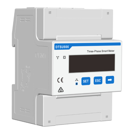
- Page 1 Three-Phase Smart Energy Meter Quick Installation Guide DTSU666-20 DTSU666-20-QIEN-Ver13-202302...
-
Page 2: Target Group
Applicability This manual is applicable to Sungrow Three-phase Smart Energy Meter. DTSU666-20 Keep the manual in a convenient place for future reference. The latest manual can be acquired at support.sungrowpower.com. Target Group Only qualified personnel with the following skills are allowed to perform the work described in this document: Training in the installation and commissioning of the electrical systems. -
Page 3: Delivery Contents
3 CTs if the product is sold to the European region and 2 CTs if the product is sold to the Australian region. NOTICE Contact SUNGROW or the distributor in case of any damaged or missing components. Three-phase Smart Energy Meter dimensions 65.5 mm... - Page 4 Three-phase Smart Energy Meter and its terminals 4:!48!47!45!44!42!:3!:2 :!!8!!!7!!!5!!!4!!!2! COMM COMM DTSU666-20 Smart Meter D TS U666-20 Smart Meter AC 3X57.7/100V...3X240/415V 50/60Hz 1.2W AC 3X57.7/100V...3X240/415V 50/60Hz 1.2W CT : * /0.3 3...
- Page 5 The meter ports are shown as follows, where the CT port is used to connect the CT to detect the current, and L1, L2, L3, N ports are used to detect the voltage. COMM COMM DTSU666-20 Smart Meter D TS U666-20 Smart Meter...
-
Page 6: Installation
Installation Mount the Smart Energy Meter to a 35 mm DIN rail. Hook it into the top edge of the rail and press down until it snaps into place. Cable Connection Step 1 Turn off solar switch, load switch, main switch and other power switches, and secure them against reconnection. - Page 7 Step 4 Connect wires to the terminals on the Smart Energy Meter, as shown below. Scenario 1:Three-phase hybrid inverter + Three-phase PV inverter + Three-phase grid Grid Load Hybrid Inverter Load PV Inverter COMM DTSU666-20 Smart Meter AC 3X57.7/100V...3X240/415V 50/60Hz 1.2W CT: */ 0.333V COMM DTSU666-20 Smart Meter Load...
- Page 8 Scenario 2:Three-phase hybrid inverter + Single-phase PV inverter + Three-phase grid Load Grid Hybrid Inverter Load PV Inverter COMM DTSU666-20 Smart Meter AC 3X57.7/100V...3X240/415V 50/60Hz 1.2W CT: */ 0.333V COMM DTSU666-20 Smart Meter Load UL 61010-1:2012, AMD1:2019 801681 AC 3X57.7/100V...3X240/415V 50/60Hz 1.2W CT: */ 0.333V...
- Page 9 Scenario 3:Single-phase hybrid inverter + Three-phase PV inverter + Three-phase grid Load Grid Hybrid Inverter Load PV Inverter COMM DTSU666-20 Smart Meter AC 3X57.7/100V...3X240/415V 50/60Hz 1.2W CT: */ 0.333V COMM DTSU666-20 Smart Meter Load UL 61010-1:2012, AMD1:2019 801681 AC 3X57.7/100V...3X240/415V 50/60Hz 1.2W CT: */ 0.333V...
- Page 10 Scenario 4:Single-phase hybrid inverter + Single-phase PV inverter + Three-phase grid Load Grid Hybrid Inverter Load PV Inverter COMM DTSU666-20 Smart Meter AC 3X57.7/100V...3X240/415V 50/60Hz 1.2W CT: */ 0.333V COMM DTSU666-20 Smart Meter Load UL 61010-1:2012, AMD1:2019 801681 AC 3X57.7/100V...3X240/415V 50/60Hz 1.2W CT: */ 0.333V...
- Page 11 Scenario 5:Single-phase hybrid inverter + Single-phase PV inverter + Single-phase grid Load Grid Hybrid Inverter Load PV Inverter COMM DTSU666-20 Smart Meter AC 3X57.7/100V...3X240/415V 50/60Hz 1.2W CT: */ 0.333V COMM DTSU666-20 Smart Meter Load UL 61010-1:2012, AMD1:2019 801681 AC 3X57.7/100V...3X240/415V 50/60Hz 1.2W CT: */ 0.333V...
- Page 12 Step 5 After the meter is connected, please check the CT direction and cable installation carefully. The arrow on the CT should always point to the load side. Hybrid Inverter Load COMM DTSU666-20 Smart Meter AC 3X57.7/100V...3X240/415V 50/60Hz 1.2W CT: */ 0.333V COMM...
- Page 13 Step 6 For inverter cable connection, refer to the user manual of the corresponding inverter. Step 7 Cover the Smart Energy Meter with the insulating cover or contact protection of the sub-distribution. Switch on the power supply to the sub-distribution. Displayed function From the displayed interface, the electrical parameter and energy data are all primary side data (that is, the multiplied by current and voltage ratios).
- Page 14 First channel Second channel Combined phase Combined phase active power active power =1.090kW =1.101kW Second channel First channel Combined phase Combined phase active power active power =1.100kW =1.101kW Second channel First channel Combined phase Combined phase power factor active power PFt=0.500 =1.100kW First channel...
-
Page 15: Programming Function
Programming function The parameters of the meter equipped only with 100A/0.333VCT have been set before delivery, and can be installed directly after acceptance, without setting the parameters again, and the meters equipped with the rest of the CT and Rogwski coils need to set their parameters before installation. Programming Parameter Parameter Value range... -
Page 16: Troubleshooting
Programming Parameter Button description: “SET” represents “confirm” or “cursor shift” (when input digits), “ESC” represents “exit”, and “→” represents “add”. The password is 701 by default. When input digits, “ ” can be used as cursor “ - ”motion button, “ ”is “add”...
Need help?
Do you have a question about the DTSU666-20 and is the answer not in the manual?
Questions and answers