Table of Contents
Advertisement
Quick Links
Advertisement
Table of Contents

Related Manuals for ADTI 210S

Summary of Contents for ADTI 210S
-
Page 1: 210S User Manual
ADTi 210S User Manual V1.01 2023.07.01... -
Page 2: Table Of Contents
Use of the wild card version ........................ 12 Device installation Cables connection How to operate DJI M300 with 210S ..........................21 Skyport installation and connection DJI X-port with M300 payload camera Post-flight operations and data collation ....................30 rollover preparation ..........................30 Operations related to data transfer .................... -
Page 3: Product Description
The new generation of 210S is only 135*135*112mm in size and 950g in weight, so that middle size multicopter such as DJI M300 can carry the 210S full-frame cameras. -
Page 4: Item List
item list Camera body*1 Data storage module*1 (one standard configuration, additional purchase) TF card*1 Data reader and accessories*1 Data reading interface dust cover*1 Skyport adapter box (optional)*1 Universal intelligent control box (optional) *1 Three-axis brushless gimbal and accessories (optional)*1 Cleaning kit*1 The main parameters ⮚... -
Page 5: Installation And Use
Installation and use Camera system detail list Mounting of M300 three-axis self-stabilizing gimbal:... - Page 6 2. M300 SKYPORT adapter mount:...
- Page 7 3. Fixed-wing mission storage load:...
-
Page 8: Camera Preparation And Accessories Instructions
Camera Preparation and Accessories Instructions Cameras and Accessories camera body 1. Storage indicator light, when the light flashes, it means that the camera is reading and writing the memory card; 2. Storage module installation slot; 3. Camera system status indicator light; 4. - Page 9 selection; 2. When the module is installed, insert it according to the guide rail, and there will be a popping sound feedback when it is installed in place; 3. When picking it up, turn the knob in the direction indicated by the arrow in the picture below, and the module will pop up automatically, then just pull it out.
- Page 10 Universal voice intelligent control box Skyport adapter box 1. Used to mount 210S camera on M300 aircraft; 2. Compatible with conversion of DJI PSDK control protocol; 3. The camera operation log is recorded in the TF card.
- Page 11 Three-axis brushless gimbal 1. The kit includes 1 set of three-axis brushless gimbal main body, 4 heightening foam shafts, and 4 heightening shaft anti-drop clamps; 2. Before installing the gimbal, be sure to install the heightening shaft on the aircraft stand to avoid damage to the camera lens when it touches the ground.
-
Page 12: Preparation
Preparation 1. Use the data transfer device, install the data storage module and log TF card, and clear the data card through 210S-PREDATA software; 2. Press the memory module into the camera according to the limit hole for use. Use of the wild card version device installation 1. - Page 13 2. Install with the corresponding structural parts of the aircraft through the bottom shock- absorbing mounting bracket;...
- Page 14 3. Installation example (fixed wing camera mount box installation):...
-
Page 15: Cables Connection
line connection 1. Integrate the aircraft with the camera through the control module; 2. Connect the J30-15 plug in the above picture to the corresponding plug on the top of the camera, and fasten the screws, and plug and unplug the interface strictly when the power is on;... - Page 16 5. Equipped with platform electrical connection port: Terminal number table USART_TX USART_RX GND_EX CAN_L CAN_H THREE Signal Description...
- Page 17 thread network illustrate color A camera independent feedback X camera independent Normal high feedback level 3.3V, S camera feedback independent falling pulse feedback after taking pictures, W camera width 10ms independent feedback D camera independent feedback GND_EX black ground wire THREE white trigger signal...
- Page 18 Use and operation Control box operation and use This version is integrated, and the operation and control of the camera are all done through the smart camera control box. The camera control box controls the camera, configures the camera, obtains the camera status, records the working day of the camera, broadcasts the current status of the camera, and can observe part of the working status of the camera on the camera.
- Page 19 MODE 1 JPEG 100-800 Multi-rotor low-speed flight, that is, it is used when ground speed <=12m/s It is recommended to use when the light is low, cloudy, early morning and evening when there is not enough light MODE 2 JPEG 100-800 1250 It is used when the light...
- Page 20 always on, it enters the standby state one after another, and the camera panel can be operated; b. Press the button once, "Da" with a long sound of the bee tweet, and the state lights are extinguished at the same time. At this time, the switch is unlocked; press the voice prompt, and press the power button again within 5 seconds.
-
Page 21: How To Operate Dji M300 With 210S
M300 adaptation version solution use Skyport installation and connection 1. Insert the PSDK adapter module into the connector on the top of the camera, as shown below: 2. Tighten the five mounting screws, as shown in the figure below, the positions are circled by the white silkscreen:... - Page 22 3. If mounted via a three-axis gimbal: 4. Installation of landing gear heightening accessories:...
-
Page 23: Dji X-Port With M300 Payload Camera
5. Format the TF card into FAT format, insert it into the card slot of the adapter seat in the PSDK adapter box/gimbal camera, and insert the card according to the screen printing on the front of the card slot; 6. - Page 24 Use and operation of M300 payload camera camera configuration 1. Enter the M300 flight route 2. On the new camera page of the aerial map, manually output the resolution, sensor, and focal length information, as shown in the figure below; 3.
- Page 25 4. After the display of real-time data is turned on, the main interface of the remote control will have a floating window displaying camera status information, which will display the switch status, parameter configuration gear, trigger number, number of shots taken by each sub-camera at the time of startup, and gimbal yaw angle YAW (this item will not be displayed if the gimbal is not used);...
- Page 27 serial camera Format Sensitivity Shutter Instructions for number mode speed JPEG 100-800 1000 JPEG 100-1600 JPEG 100-800 1250 After starting up, you must select the required operating parameters in the PAYLOAD setting page - mode selection column according to the operating conditions. 7.
- Page 28 Three-axis gimbal use 1. After the M300 recognizes the gimbal, the gimbal setting menu is as follows: 2. Control the gimbal through the thumbwheels on the left and right shoulders of the remote control: 3. Use the compass on the remote control display as a reference, point the aircraft head to the north, and the heading angle displays "000", then adjust the gimbal to the neutral position through the dial, click "Reset gimbal parameters"...
- Page 29 4. Use the dial to adjust the gimbal to the desired angle, change the gimbal mode to follow mode, and you can fly:...
-
Page 30: Operations Related To Data Transfer
5. In case of special circumstances, when the route task cannot set the photo point, it can automatically take pictures at regular intervals, as shown in the interface shown below; a. Single shot: After sending the camera command, the camera takes a single photo; b. -
Page 31: Post-Flight Operations And Data Collation
3. The HUB USB3.0 port (marked 2 in the above figure) can be used to connect extended USB devices such as mouse, keyboard, and USB storage device, but it cannot be connected to the USB port of a PC/MAC computer. Operations related to data dump See "ADTI 210S User Mnual" for details. - Page 32 log lookup 1. After the flight is over, pull out the TF card from the module (wild card, PSDK), and check the csv file named by date and time in the LOG folder through the card reader; 2. Description of the main information of the log content: Header name illustrate...
-
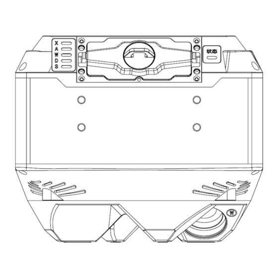
Page 33: Attachment Camera 2D View And Mounting Holes Position
2. PSDK writes directly after reading from the aircraft altitude GPS altitude 1. The content of the wild card version is empty and needs to be obtained from the aircraft POS file 2. PSDK writes directly after reading from the aircraft Relativeheigh Height to ground in meters... - Page 34 Attachment 1: 1:1 Rubbing Map of Field of View Window and Positioning Hole *Note: You can print this page on A4 paper at a ratio of 1:1, rubbing and opening holes. Before opening, please measure and check whether the expansion space is consistent with the mark.
Need help?
Do you have a question about the 210S and is the answer not in the manual?
Questions and answers