
Subscribe to Our Youtube Channel
Related Manuals for Stulz Prodigy IROW CW


Summary of Contents for Stulz Prodigy IROW CW
- Page 1 English ––– STULZ the natural choice Release 04.21 Operating instructions Prodigy IROW CW High density air conditioner 230/1/50-60...
-
Page 3: Table Of Contents
Table of contents Safety Directions ......................... 6 1.1 General information ....................... 7 1.2 Safety and environmental requirements ................ 8 1.3 Residual risks ........................ 9 Unit identification ......................10 Components and operating principle ................12 3.1 Intended and non-intended use ................... 12 3.2 Application limits ...................... - Page 4 7.5 General appliance cleaning procedures ..............45 Troubleshooting ....................... 46 Uninstalling the unit ......................47 10. Accessories / options ....................... 48 10.1 Condensate pump installed inside the unit – CONDPUMP.......... 48 10.2 3-way valve – 3WAYVAL .................... 49 10.3 External frame ......................49 11.
- Page 5 STULZ reserves the right to update the product and the relevant manual without having to update products and manuals sold previously except under exceptional circumstances.
-
Page 6: Safety Directions
This manual must be kept by the customer and made available to the installation, commissioning, use and maintenance personnel. An informative document on the REACH Regulation is available. Please view it on web site https://www.stulz.it/it/azienda/media/informazioni-generali/ Symbols on this manual: SYMBOLS ON THIS MANUAL... -
Page 7: General Information
Cooling water additives have an acidic effect on skin and eyes. Wear safety glasses and safety gloves • The unit may only be used to cool according to the Stulz specification • Before any maintenance operation, read and follow instructions in the corresponding chapter. -
Page 8: Safety And Environmental Requirements
Chapter 7. Independent conversion and manufacture of replacement parts The system may only be converted or modified after consultation with STULZ. Original replacement parts and replacement parts/accessories authorized by STULZ are an aid to safety. -
Page 9: Residual Risks
Residual risks During transport and installation Area Danger Risk Preventive measures Under the Defective lifting system of the unit Contusions, Keep away from dangerous area during handling of the unit. unit that causes its fall. traumas Near the Unstable or unsuitable support of Contusions, Be sure that the unit has adequate support in relation with its unit... -
Page 10: Unit Identification
2. Unit identification Name-plate This unit can be identified by the name- plate that includes information regarding its correct use. The name-plate is located in two copies on the outer casing of the unit (generally on one of the sides) and on the panel that closes the electric box. - Page 11 Coding Configuration Thermal medium Nominal cooling capacity Airflow Water valve Control Power supply Piping connection R A W C4 C 3 A 20 S B B = standard unit P = connection from the top with condensate pump S = AC radial fan E = EC radial fan 20 = 230 V/ 1 Ph / 50÷60 Hz A = SEC.blue...
-
Page 12: Components And Operating Principle
As well, STULZ Prodigy IRow conditioners cannot be used outside safety limits specified on the name-plate. Conditioners must not be transported or used in positions that differ from those for which they were designed. -
Page 13: Application Limits
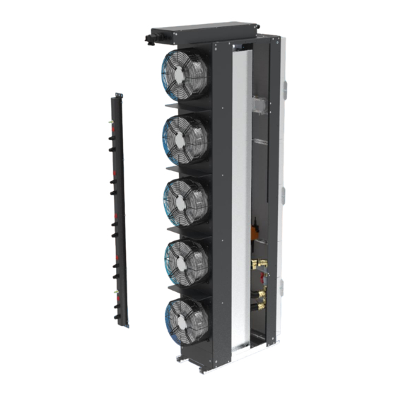
Humidity Component layout STULZ Prodigy IRow units are installed between two server racks in open loop configuration. They take air from a hot aisle of the room, cool and deliver it to a cold aisle, where it is sucked in by the server rack fans. - Page 14 Air filters (only in open loop models) Fans Air inlet Air outlet Air-to-water heat exchanger 2-way modulating valve Air outlet Air inlet Water connections Condensate drip tray E/iROW-CW/0421/14...
-
Page 15: Working Modes
Working modes Cooling Air is sucked in by the radial fans, is filtered (only in open loop units) and then it is cooled passing through the chilled water heat exchanger. After treatment, air is delivered through the frontal opening. Cooling capacity is modulated by SEC.blue in different ways, acting on the 3-way valve and / or on the fan speed, according to the temperature measured by the return probes. -
Page 16: Hydraulic Circuit Components
Hydraulic circuit components Air-to-water heat exchanger It is made of copper pipes and aluminium fins. In this coil, heat is exchanged between inner air and chilled water. It is not suitable to either corrosive or saline environments. Surface has hydrophilic treatment. 2-way modulation valve 2-way valve is used when CW unit is connected to a chilled water distribution system with variable flow;... -
Page 17: Motors
STULZ engineering division department. STULZ conditioners come with a set of devices designed to ensure proper operation. Tripping by any one of these automatic safety devices is a sign of a malfunction and it is absolutely necessary to eliminate the cause. - Page 18 Expansion tachometric board (with more than 3 EC fans) This expansion board receives the three V1 – V2 – V3 signals 0÷12 V from SEC.blue and duplicate them to control speed of 3 couples of fans. This board receives a tachometric signal as a feedback from each single fan to check whether it runs.
- Page 19 RFS dirty filter pressure switch (only in open loop models) RFS gives a dirty filter signal (only with open loop units), shown both on the display and on a voltage-free contact. It indicates when it is necessary to clean or replace the air filter. Range : 20 –...
- Page 20 SEC.Blue I/O CONTROLLER This microprocessor-based electronic board is equipped with a set of terminals which are necessary to connect the board to the controlled devices (e.g. valves, compressors, fans). Software with working logic and parameter settings are written in the EEPROM so that they remain permanently stored even in case of power failure.
-
Page 21: Unpacking And Inspection
4. Unpacking and inspection INSPECTION STULZ products are delivered ex-works. All units have been individually inspected in all their components and been carefully packaged before the delivery. Immediately inspect the unit upon receipt of the goods: • Make sure that it has been transported in the correct position. Note any unsuitable shipping conditions on the shipping document. - Page 22 Risk of personal injuries during materials handling Material handling and unpacking must be done only by trained personnel with suitable individual protection devices (i.e. gloves, glasses, helmet, shoes) LIFTING AND TRANSPORT Risk of downfall of heavy units Capacity of lifting device must be appropriate for the weight of air conditioner. Load must be balanced to avoid tilting.
- Page 23 Standard packing doesn’t protect air conditioner from rain and bad weather. Standard packing is not suitable for seafreight. Standard packing is not suitable for airfreight. Following information can be found on packing: • STULZ logo • unit code • accessories put in the packaging • warning symbols If unit is stored before installation, comply with following instructions: •...
-
Page 24: Installation
5. Installation Positioning the unit iRow air conditioners are not provided with either lateral or top or door panels. Therefore, they must be installed inside a frame with suitable protection. In open loop version they must be installed between two server racks. Installation at an end of a row is not recommended because there is a mix of hot and cold air. - Page 25 In closed loop version they must be installed beside a rack. A closed air circuit must be created between the rack and the unit, installing suitable plenums. A/C unit Server rack Furthermore, check that: • there’s room enough for an easy installation and maintenance of the unit: please check dimensional drawings, with particular attention to the accessibility of water connections and wiring.
- Page 26 E/iROW-CW/0421/26...
- Page 27 Open loop AC fans EC fans Closed loop AC fans EC fans E/iROW-CW/0421/27...
- Page 28 E/iROW-CW/0421/28...
- Page 29 Detail 1 Detail 2 (position of fixing points on lateral-bottom frame) Detail 3 E/iROW-CW/0421/29...
- Page 30 Detail 4 (position of fixing points on bottom side) E/iROW-CW/0421/30...
- Page 31 Only with Only with EC fans EC fans Dimensions of multi-switch bar (3 fans) E/iROW-CW/0421/31...
- Page 32 Only with Only with EC fans EC fans Dimensions of multi-switch bar (5 fans) E/iROW-CW/0421/32...
-
Page 33: Hydraulic Connection
Hydraulic connection Prodigy RAW air conditioners must be connected to a circuit with chilled water, including either a chiller or a dry cooler or a cooling tower. For chilled water circulation, pumps have to be provided. These pumps must be selected according to total pressure losses through the hydraulic circuit. Pressure losses through RAW air conditioners are shown in the technical data sheet at the end of this manual. - Page 34 Coefficient of correction for pressure losses through the hydraulic circuit, using monoethylene glycol. chilled water average temperature Hydraulic connections in RAW units are screw type, with 1” diameter for all models. Holes for water pipes are placed both on the base and on the top panel of the unit. When pipes pass from the top, loosen the ring nut of water connectors on the unit and rotate them by 180°...
- Page 35 In case some gaskets are missing, use always glycole-proof rubber gaskets. Apply teflon gasket on the nipple and tighten it to the female connector on the unit. Application of Teflon gasket (not supplied) to the nipple Insulate water pipes with anti-diffusion material, to avoid heat exchange with ambient air and consequent condensation of humidity in it on the pipes.
-
Page 36: Condensate Drain Connection
Condensate drain connection Condensate drain connector is placed on the rear side of the drain pan, under the CW coil. Connection diameter is 16 mm for all models. If condensate pump is not present, a PVC pipe with 0,3 m length is provided. This pipe has to be routed outside the unit through the opening on its base used also for pipes and electric cables. -
Page 37: Electric Connections
Electric connections It's absolutely necessary, before making any connections, to check the supply voltage with a tester. The voltage that is measured must correspond with the voltage indicated on the unit label. The installer must install, upstream from the unit, an isolating switch with fuse and capacity as specified on the label in order to permit maintenance on the machine with total absence of electricity. - Page 38 • The electric box is supplied loose on the top of the unit. It is provided with 4 lateral inserts for fixation to the rack frame. The electric box is plugged to internal components of the unit. When inserting the unit into the rack, it is possible to unplug the electric box and put it into the rack in a second moment.
-
Page 39: Telemonitoring
Connections and power supply plate: Connector RJ45 for Ethernet (see paragraph 5.6) Connector RJ11 for Telemonitoring (see paragraph 5.5) Telemonitoring Telemonitoring net is via RJ11 connector. Units have to be linked each other in a serial RS485 net using pin-to-pin phone cables of the following type: data cable 2CP AWG24 with modular phone plug 6/4. -
Page 40: Ethernet Connection
MODBUS PROTOCOL Set parameter C.4.3.1.1.3 to MODBUS 2015 The SEC.blue controller can communicate with the software installed on host computer which displays the setup parameters, the controller states and alarms. The parameter C.4.3.1.1.3 sets the protocol for the RJ11 connector of the board. In the system (see figure below) there is no gateway managing the communication. -
Page 41: Start-Up
6. Start-up Before you first start up the system install and connect it up as described in the “Installation” chapter. • Make sure the main switch is turned off and that the system is isolated from power mains. • Check that all power switches in the electric system have been turned off. •... -
Page 42: Maintenance
7. Maintenance Safety instructions Installation and intervention on air conditioners must be made in full compliance with specific national regulations for accident prevention, with particular reference on electric and refrigerant equipment. Failure to comply with these regulations might be dangerous to people and environment. -
Page 43: Preventive Maintenance Program
Preventive maintenance program Every month • WATER CIRCUIT: check tightness of the circuit. Every 3 months • AIR FILTERS (only in open loop models): check the condition of the filters and replace them if necessary (dirty filter alarm). • HEAT EXCHANGERS: check that the heat exchangers are efficient and not clogged or dirty. •... - Page 44 Push the bracket up and extract it. Then the filter can be removed. Spare filters must have filtering medium with the same thickness and density as the original one. A A set of spare filters can be ordered to your local STULZ service partner. E/iROW-CW/0421/44...
-
Page 45: Water Circuit
Water circuit Check visually tightness of water circuit. In addition, a level indicator in the water tank (if present), can be useful to see changes of water quantity. Water going out of water circuit is replaced by air, which reduces cooling capacity of the unit and might damage circulation pump. General appliance cleaning procedures Never use caustic or acid substances to clean any part of the conditioner. -
Page 46: Troubleshooting
Check voltage on power supply missing cables. Repair the broken cable or restore the missing connection Faulty controller Contact Stulz service Controller is working, Faults blocking the unit Look for alarms on the display. but the rest of the Contact Stulz service... -
Page 47: Uninstalling The Unit
PROBLEM CAUSE POSSIBLE SOLUTION Alarm: Dirty filter Air filter is clogged Replace the filter Air filter pressure switch faulty Replace the differential pressure switch Pipes to the dirty filter pressure Clean and re-position plastic pipes switch clogged or bended Alarm: Water Room humidity is over the maximum Check passage of air from the detector (if water... -
Page 48: Accessories / Options
10. Accessories / options Condensate pump installed inside the unit – CONDPUMP 10.1 A pump is installed inside the unit when condensate evacuation by gravity is not possible. With condensate pump, the opening for cable and pipes passage through the base cannot be used. -
Page 49: 3-Way Valve - 3Wayval
Troubleshooting Fault: Pump runs all the time 1. Is float positioned with the magnet uppermost? 2. Is the reservoir lid (sensor) located firmly onto the reservoir, with the float located inside the reservoir, around the sensor column? 3. Is there sludge inside the reservoir, preventing float from resting on the bottom? (This may occur if pump has been in operation for some time without cleaning. -
Page 50: Technical Data
11. Technical data Notes on technical data sheets: Nominal conditions Closed loop: return air temperature 45°C / RH 15% Open loop: return air temperature 30°C / RH 30% EWT (all models) = 7°C Water dT (all models) = 5°C Gross cooling capacities (including power dissipated by fans) Refrigerant: water without additives Total pressure losses through the water circuit inside the unit. - Page 51 E/iROW-CW/0421/51...
- Page 52 E/iROW-CW/0421/52...
- Page 53 RAWA1 open loop: cooling capacity WT=7-12 WT=10-15 WT=12-18 WT=15-21 Return air temperature (°C) RAWA1 open loop: water flow 4000 3500 3000 2500 WT=7-12 2000 WT=10-15 WT=12-18 1500 WT=15-21 1000 Return air temperature (°C) E/iROW-CW/0421/53...
- Page 54 RAWA7 open loop: cooling capacity 30,0 25,0 20,0 WT=7-12 15,0 WT=10-15 WT=12-18 WT=15-21 10,0 Return air temperature (°C) RAWA7 open loop: water flow 6000 5000 4000 WT=7-12 3000 WT=10-15 WT=12-18 WT=15-21 2000 1000 Return air temperature (°C) E/iROW-CW/0421/54...
- Page 55 RAWB1 open loop: cooling capacity WT=7-12 WT=10-15 WT=12-18 WT=15-21 Return air temperature (°C) RAWB1 open loop: water flow 7000 6000 5000 4000 WT=7-12 WT=10-15 3000 WT=12-18 WT=15-21 2000 1000 Return air temperature (°C) E/iROW-CW/0421/55...
- Page 56 RAWA6 closed loop: cooling capacity WT=7-12 WT=10-15 WT=12-18 WT=15-21 Return air temperature (°C) RAWA6 closed loop: water flow 4500 4000 3500 3000 2500 WT=7-12 WT=10-15 2000 WT=12-18 WT=15-21 1500 1000 Return air temperature (°C) E/iROW-CW/0421/56...
- Page 57 RAWB2 closed loop: cooling capacity 35,0 30,0 25,0 20,0 WT=7-12 WT=10-15 15,0 WT=12-18 WT=15-21 10,0 Return air temperature (°C) RAWB2 closed loop: water flow 6000 5000 4000 WT=7-12 3000 WT=10-15 WT=12-18 WT=15-21 2000 1000 Return air temperature (°C) E/iROW-CW/0421/57...
- Page 58 RAWC4 closed loop: cooling capacity 40,0 35,0 30,0 25,0 WT=7-12 20,0 WT=10-15 WT=12-18 15,0 WT=15-21 10,0 Return air temperature (°C) RAWC4 closed loop: water flow 7000 6000 5000 4000 WT=7-12 WT=10-15 3000 WT=12-18 WT=15-21 2000 1000 Return air temperature (°C) E/iROW-CW/0421/58...
- Page 59 Water pressure loss (kPa) RAW A1/A7 - RAW A6/B2 RAW B1 - RAW C4 1000 2000 3000 4000 5000 6000 7000 Water flow (l/h) E/iROW-CW/0421/59...
- Page 60 Coefficient of correction of cooling capacity with 20% monoethylene glycole 0,990 0,985 0,980 0,975 WT=7-12 0,970 WT=10-15 WT=12-18 0,965 WT=15-21 0,960 0,955 0,950 Return air temperature (°C) Coefficient of correction of cooling capacity with 30% monoethylene glycole 0,970 0,960 0,950 0,940 0,930 WT=7-12...
- Page 61 Coefficient of correction of cooling capacity with 40% monoethylene glycole 0,960 0,940 0,920 0,900 WT=7-12 0,880 WT=10-15 WT=12-18 0,860 WT=15-21 0,840 0,820 0,800 Return air temperature (°C) E/iROW-CW/0421/61...
Need help?
Do you have a question about the Prodigy IROW CW and is the answer not in the manual?
Questions and answers