Table of Contents
Advertisement
Quick Links
Models TVC-2 and TVC-6
Advanced Vent Controllers
System Installation Manual
TFP1279
JANUARY 2024
Scan the QR code or enter the URL
in a web browser to access the most
up-to-date electronic version of this
document. Data rates may apply.
docs.jci.com/tycofire/tfp1279
1467 Elmwood Avenue, Cranston, RI 02910 | Telephone +1-401-781-8220
© 2024 Johnson Controls. All rights reserved. All specifications and other information shown were current as of document revision date and are subject to change without notice.
johnsoncontrols.com
Advertisement
Table of Contents
Troubleshooting

Related Manuals for Johnson Controls tyco TVC-2


Summary of Contents for Johnson Controls tyco TVC-2
- Page 1 Data rates may apply. docs.jci.com/tycofire/tfp1279 1467 Elmwood Avenue, Cranston, RI 02910 | Telephone +1-401-781-8220 © 2024 Johnson Controls. All rights reserved. All specifications and other information shown were current as of document revision date and are subject to change without notice. johnsoncontrols.com...
-
Page 2: Table Of Contents
Table of Contents GENERAL ..........................4 Copyrights and Safety ..........................4 Safety Guidelines ............................4 General Safety Information ........................4 Cautions and Warnings ..........................5 Maintenance and Troubleshooting Warnings ..................5 Dry Pipe Nitrogen Inerting (DPNI) ......................6 Dry Pipe Nitrogen Inerting Equipment ..................... 6 Tyco Vent Controller .......................... - Page 3 Alarm Settings Page ..........................22 Alarm Datalog Page ..........................23 Datalogging Settings Page ........................23 System Settings Page .......................... 24 Operations Events Page ........................24 Information Page ..........................25 COMMISSIONING AND STARTUP PROCEDURE ............... 26 Commissioning and Startup Guidelines ....................26 Pre-Start Up ............................
- Page 4 Maintenance and Troubleshooting Warnings ..................42 Routine Checks ............................42 Oxygen Removal Vent Maintenance ....................43 In-Line Filter Replacement Instructions ....................43 SYSTEM WIRING ........................44 © 2024 Johnson Controls Inc. All Rights Reserved. JCI Proprietary Information. TFP1279 JANUARY 2024 Page 3 of 44...
-
Page 5: General
Johnson Controls Inc., assumes no liability resulting from any errors or omissions in this manual, or from the use of the information contained herein. Johnson Controls Inc., reserves the right to make changes to this manual and the data sheets herewith at any time, without prior notification. -
Page 6: Cautions And Warnings
Cautions and Warnings CAUTION: Do not install the Nitrogen Generation Systems in an area where ammonia, sulfur dioxide, hydrogen sulfide, mercaptans, chlorides, chlorine, oxides of nitrogen, acid fumes, solvent vent vapors, and ozone vapors or similar contaminates exist. The equipment can be damaged by ammonia and other vapors shortening life. -
Page 7: Dry Pipe Nitrogen Inerting (Dpni)
SYSTEM AND PRODUCT INFORMATION Dry Pipe Nitrogen Inerting (DPNI) Dry Pipe Nitrogen Inerting technology is used to control oxygen corrosion in dry pipe and/or preaction fire sprinkler systems. DPNI is executed by employing a fill and purge differential pressure cycle (breathing) within the sprinkler pipe network. -
Page 8: Tyco Vent Controller
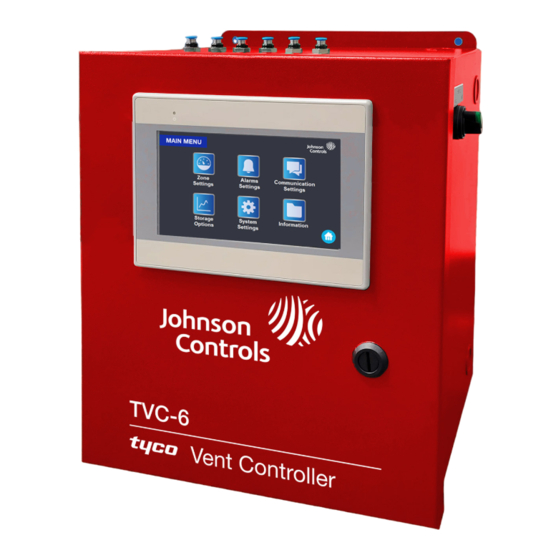
Tyco Vent Controller The Models TVC-2 and TVC-6 Tyco Vent Controller (TVC), herein called the TVC or vent controller, provide automatic oxygen venting, monitoring of nitrogen/oxygen concentration levels, and monitoring of the sprinkler system pressure within each dry pipe/preaction fire sprinkler system. As a fire sprinkler system is filled with a continuous supply of nitrogen gas from the nitrogen generator system, the vent, installed on the sprinkler system riser, allows oxygen rich gas to be vented from the fire sprinkler system. -
Page 9: Tyco Vent Controller Assembly
Tyco Vent Controller Assembly Figure 1: Models TVC-2 and TVC-6 System assembly Model TVC-2 Model TVC-6 Item Description Power Switch Oxygen Sensor Manifold Block Oxygen Sensor Interface Logic Board Pressure Transducer Electrical Power and Signal Distribution Block, see Figures 3a, 3b Manifold with Solenoids¹... -
Page 10: Oxygen Removal Vent
Oxygen Removal Vent To completely remove the oxygen in a dry pipe and preaction fire sprinkler system, it is necessary to install a vent on the main riser of each fire sprinkler system. Vents allow for a system to breathe, which requires a 3 psi to 5 psi (0.2 bar to 0.3 bar) pressure range to facilitate removal of oxygen gas from the system. -
Page 11: Technical Specifications
TECHNICAL SPECIFICATIONS Physical Specifications Table 1a: Physical Specifications Models TVC-2 TVC-6 Dimensions 10 in. (254 mm) W x 12 in. (305 mm) H 12 in. (305 mm) W x 14 in. (356 mm) H x 6 in. (152 mm) D x 8 in. -
Page 12: Environmental Specifications
Environmental Specifications Table 1b: Environmental Specifications Location Dry Indoor Use Altitude Up to 6,560 ft (2,000 m) Temperature Range 32°F - 122°F (0°C - 50°C) Electrical Specifications Table 1c: Electrical Specifications 120 VAC OK, I am going to writ- 240 VAC, Single phase, Cabinet Power Supply 50 - 60 Hz Power Consumption... -
Page 13: Start-Up And Operational Procedures
START-UP AND OPERATIONAL PROCEDURES Installation This section describes how to install the nitrogen generator. Installation Overview Installation of the Tyco Vent Controller (TVC) requires four steps: 1. Mount the cabinet in the appropriate location. 2. Connect the dedicated power supply to the cabinet (can be connected to the same power supply as the nitrogen generator). - Page 14 Step 1: Mount the Vent Controller Cabinet The Vent Controller is designed to be mounted directly to the wall at the appropriate location. Several factors should be considered in choosing the proper mounting location for the controller cabinet: • Access to required power supply (dedicated circuit) •...
- Page 15 TVC using 5/32 in. flexible tubing. The TAV-DQ, TAV-D or TSV-D vents can be used with the TVC. The TAV-D and TSV-D require field reconfiguration for use with the TVC. Contact Johnson Controls Technical Services before proceeding. Visit the CONTACT US page at www.tyco-fire.com...
- Page 16 Step 5: Connect the Vent Controller: Output Signals (where applicable) The vent controller has a common supervisory signal that can be monitored by the facility’s building management system or building alarm system. The common supervisory signal is a Form-C contact with the following connections: •...
- Page 17 Figure 3b: Model TVC-6 Electrical connections Item Description Ethernet Ports, Not Used Normally Open (N.O.) Common Normally Closed (N.C.) Power Supply Power Connection L1 Power Connection N Power Connection G Notes: Common Supervisory Signal, Contact Rating 250 VAC/6 A d. 120 VAC – 240 VAC, Single phase, 50 Hz – 60 Hz, 0.5 A TFP1279 JANUARY 2024 Page 16 of 44...
-
Page 18: Hmi User Interface Overview
HMI USER INTERFACE OVERVIEW HMI User Interface The vent controller operation is managed through the Human-Machine Interface (HMI) LCD. The HMI provides access for setup, monitoring and control functions of the TVC. All of the pages on the HMI are accessible from the Home page. -
Page 19: Individual Zone Page
Individual Zone Page The individual Zone page displays sprinkler system pressure and nitrogen purity digitally and graphically for a sprinkler system zone. Tap the Start Venting button to initiate venting, and the Leak Rate Check button to initiate a sprinkler leak rate test, and to digitally display the leak rate. Tap the Event Log button to display and review historical information. -
Page 20: Leak Rate Check
Leak Rate Check The TVC can perform a leak rate check of the sprinkler system on an individual sprinkler system basis. The leak rate check can be used to determine the leak rate of the sprinkler system for compliance with the NFPA allowable leak rates. -
Page 21: Vent Control Page
At the completion of the Leak Rate Check: When the Leak Rate Check is complete, the systems status is as follows: • Status display indicates Test Complete. Done button is shown. • Actual leak rate is shown. • Leak rate is logged in the Events Log. •... -
Page 22: Main Menu Page
Main Menu Page The Main Menu page provides access to the following pages: Zone Settings • Alarm Settings • Information • • Storage Options • System Settings Access: Home page → Main Menu button. Tap the appropriate button to set or to change the appropriate function. Zone Settings Page The Zone Settings page provides access to change sprinkler zone name(s) and add or delete additional sprinkler zones to the TVC. -
Page 23: Alarm Settings Page
The Zone Settings page also provides access to change sprinkler zone operating pressure. Access: Home page → Main Menu button → Zone Settings button→ More button. Zone operating pressure Tap to edit Alarm Settings Page The Alarm Settings page displays any alarms provides access to adjust the Venting Alarm Time (default is 14 days) and the Low Air Alarm Pressure. -
Page 24: Alarm Datalog Page
Alarm Datalog Page The Alarm Datalog page displays any alarms associated with Venting Alarm Time and the Low Air Alarm Pressure. Access: Home page → Main Menu button on → Alarms button → Alarms Datalog button. Datalogging Settings Page The Datalogging Settings page provides access to back up the Historical Data or remove the USB drive in the TVC. -
Page 25: System Settings Page
System Settings Page The System Settings page provides access to clock and calendar settings. Note: If the TVC needs to be recommissioned, tap the button to reset the TVC to the default settings. Access: Home page → Main Menu button → System Settings. JCI internal use only Tap the button to reset the TVC to default... -
Page 26: Information Page
Information Page The Information page displays the nitrogen generator’s model number, serial number, PLC and HMI software version numbers. The Information page provides access for the Johnson Controls contact information, Site Location information, Building Owner’s contact information, and Service Contractor contact information. -
Page 27: Commissioning And Startup Procedure
COMMISSIONING AND STARTUP PROCEDURE Commissioning and Startup Guidelines Only qualified personnel should commission the new equipment into service once it is installed. Note: When the vent controller is configured, there should be no reason to reconfigure. Pre-Start Up Prior to starting up the TVC install the USB memory storage drive into the USB memory location on the back side of the LCD Display. -
Page 28: Commissioning
Commissioning The vent controller commissioning must be completed for the TVC to operate. For commissioning instructions, see the Commissioning Procedure section on page 36. Start Up The TVC monitors each sprinkler system pressure and nitrogen purity individually along with storing the information into the individual sprinkler system’s memory. -
Page 29: Normal Operation
Normal Operation The vent controller monitors each sprinkler system pressure and nitrogen purity individually. The information is stored into the individual sprinkler system zone’s memory. Sprinkler System Zone Information The sprinkler system zone information is stored in memory for each sprinkler system controlled by the TVC. -
Page 30: Individual Zone Event Log Information
Individual Zone Event Log Information The individual zone Event Log information is stored on the USB Storage drive and can be reviewed from the individual sprinkler system Zone page. To review the Event Log information, perform the following steps: 1. On the Home page, tap the Sprinkler System Label field for the appropriate sprinkler system. 2. -
Page 31: Sequence Of Operation
Once in service, the Tyco Vent Controller (TVC) requires no additional intervention to function properly. TVC settings should not be altered without consulting Johnson Controls and the unit should not be powered down or bypassed for any reason other than a service or maintenance procedure as detailed in the Maintenance section on page 42. -
Page 32: Monitoring Mode
Monitoring Mode In the Monitoring mode, the TVC will release a small sampling of gas each time the sprinkler system’s pressure and nitrogen purity are checked. All data obtained from each sprinkler system is stored in the Events Log on an individual zone basis. Note: The small gas sample will not have an adverse effect on the sprinkler system operating pressure. -
Page 33: Oxygen Removal Vent
OXYGEN REMOVAL VENT Figure 5: Oxygen Removal Vent: TAV-D/DQ Specifications Stock Number: TAV-D / TAV-DQ Service Pressure: Up to 175 psig (12 bar) System Connection: 1 in. NPT Male Temperature Range: 40°F to 125°F (4.5°C to 51°C) Dimensions: 13.5 in. (W) x 7.5 in. (H) x 4.25 in. (D) (343 mm (W) X 191 mm (H) X 108 mm (D)) For use under U.S. -
Page 34: Operating Instructions
1. Verify the vent assembly has been equipped with a restricted venting orifice downstream of the backpressure regulator. Note: If the vent assembly is not equipped with a restricted venting orifice, contact Johnson Controls Technical Services. The restricted venting orifice must be installed before proceeding with the steps below. - Page 35 Figure 6a: TAV-DQ Vent Assembly Restricted venting orifice In-Line filter 5/32 in. push fitting connection to TVC Float valve Gas sample port Backpressure regulator Connection to Y-Strainer Sprinkler System with ball valve ½ in. Quick connect Isolation ball valve Figure 6b: TAV-D Vent Assembly Restricted venting orifice In-Line Filter Muffler...
- Page 36 Figure 7a: Vent Installation Schematic Figure 7b: Vent/TVC Installation Schematic 5/32 in. push fitting 5/32 in. tubing between vent and TVC 5/32 in. push fitting If the 5/32 in. push fitting is not installed in the vent, remove the muffler and install the 5/32 in. push fitting TFP1279 JANUARY 2024...
-
Page 37: Commissioning Procedure
Verify the vent assembly is equipped with a restricted venting orifice downstream of the backpressure regulator. Note: If the vent assembly is not equipped with a restricted venting orifice, contact Johnson Controls Technical Services. Based on the nitrogen generator turn-on pressure and the sprinkler system low alarm pressure, adjust the pressure setting for the backpressure regulator. -
Page 38: Tyco Vent Controller Commissioning Instructions
Tyco Vent Controller Commissioning Instructions When the vent backpressure regulator pressure is determined and set, the TVC can be turned on and commissioned. The commissioning is accomplished through the Human Machine Interface (HMI). The HMI provides access for setup, monitoring and control functions of the TVC. For HMI User Interface information, see page Error! Bookmark not defined.. -
Page 39: Vent Controller Start-Up Instructions
6. If you no not need to add additional zones, tap Finish. 7. Enter the installation location information into the HMI (recommended but not required). a. Tap the appropriate field and a keyboard appears. b. Enter the appropriate information, and tap Enter. 8. - Page 40 b. Tap Vent All Zones to initiate zone venting for all of the zones (at the same time). TFP1279 JANUARY 2024 Page 39 of 44...
-
Page 41: Commissioning Checklist
Commissioning Checklist Fire Sprinkler System: General Verify and document the quantity of dry/preaction fire sprinkler systems connected to the TVC: Yes Qty. __ Verify and document the specific names or label of each dry/preaction fire sprinkler systems connected to the TVC: Sys. -
Page 42: Programming Of Tvc
Leak check all plumbing between TVC and oxygen removal vents, repair any leaks found. Verify and document that the no leaks exist between TVC and oxygen removal vents: Note: If unable to perform any functions with the TVC, contact Johnson Controls. Visit the CONTACT US page at www.tyco-fire.com... -
Page 43: Maintenance
MAINTENANCE Safety Warning Only qualified personnel can perform inspection, testing and maintenance of the nitrogen generation equipment. Prior to any system maintenance on the nitrogen generation system, ensure that the nitrogen generator is isolated from the compressed air supply and all system risers. Ensure that the nitrogen generation system and the associated piping that is to be manipulated is completely depressurized prior to performing any maintenance. -
Page 44: Oxygen Removal Vent Maintenance
Oxygen Removal Vent Maintenance 1. The vents must be inspected annually at minimum. While isolation ball valve is in the open position, check for air/water leaks and ensure the pressure gauge is displaying normal system pressure. 2. While isolation ball valve is in the closed position, inspect the condition of the in-line filter to protect against blockage of the restricted venting orifice. -
Page 45: System Wiring
SYSTEM WIRING Figure 8: Wiring Schematic Rev. 1 TFP1279 JANUARY 2024 Page 44 of 44...
Need help?
Do you have a question about the tyco TVC-2 and is the answer not in the manual?
Questions and answers