
Subscribe to Our Youtube Channel
Related Manuals for HYXIPOWER E50-H

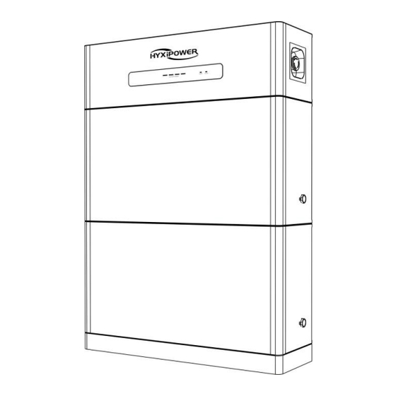
Summary of Contents for HYXIPOWER E50-H
- Page 1 User Manual E50/100/150/200-H HIGH VOLTAGE BATTERY Carefully read this battery system user instructions before using. Read and save these instructions.
- Page 2 ZHEJIANG HYXI TECHNOLOGY CO., LTD (hereinafter referred to as "HYXIPOWER"). TRADEMARKS and other HYXIPOWER trademarks are the trademarks or registered trademarks of HYXIPOWER All other trademarks mentioned herein are the properties of their respective owners.
-
Page 3: Table Of Contents
HYX-E(50~200)-H User Manual Contents CONTENTS 1. Product Introduction ............................1 1.1 Scope of Application ..............................1 1.2 Overview of Product Naming Rules ........................1 2. Safety Instructions ............................2 2.1 Interpretation of The Logo ............................ 2 2.2 Precautions/Environmental Requirements ....................... 2 2.3 Risk Factors ................................ - Page 4 HYX-E(50~200)-H User Manual Contents 5.2.3 PACK-BASE ................................ 18 5.2.4 BDU-PCS ................................19 6. LED indicator description ........................... 21 6.1 LED display and system status ..........................21 6.2 SOC lamp and capacity correspondence ......................21 7. Online monitoring ............................22 8. Routine maintenance ..........................23 8.1 Daily maintenance ..............................
-
Page 5: Product Introduction
1. Product Introduction 1.1 Scope of Application This manual is intended for the following devices: • HYX-EBDU-H • HYX-E50B-H • HYX-E50-H • HYX-E100-H • HYX-E150-H • HYX-E200-H 1.2 Overview of Product Naming Rules Hyxi energy storage high voltage stacker can provide a variety of operating modes according to... -
Page 6: Safety Instructions
The "NOTICE", "CAUTION", "WARNING" and "DANGER" items in this manual do not represent all safety items to be observed. They are in addition to all safety precautions. HYXiPOWER shall not be liable for any violation of the general safety requirements or for any violation of the safety standards for the design, manufacture and use of the equipment. -
Page 7: Risk Factors
HYX-E(50~200)-H User Manual 2. Safety instructions 2.3 Risk Factors Risks of Explosion: • Do not subject the battery module to heavy impacts; • Do not crush or puncture the battery module; • Do not dispose of the battery module in a fire. Risks of Fire: •... -
Page 8: Notes
HYX-E(50~200)-H User Manual 2. Safety instructions If a fire breaks out where the battery module is installed, please do as follows: • Extinguish the fire before the battery module catches fire; • If the battery module catches fire, please do not try to put out the fire, and evacuate immediately. - Page 9 HYX-E(50~200)-H User Manual 2. Safety instructions operation, ascent, and special equipment operation qualifications. Replacement of equipment or parts (including software) must be done by professionals or authorized personnel. Description: • Professional personnel: People who have training or experience in operating equipment and can clearly understand the various potential sources and magnitudes of hazards during equipment installation, operation, and maintenance.
-
Page 10: Limitation Of Liability
HYX-E(50~200)-H User Manual 3. Limitation of liability 3. Limitation of liability Hyxi is not responsible in the event of any of the following • It does not operate in the conditions of use described in this manual. • The installation and use environment do not comply with the provisions of the relevant international or national or regional standards. -
Page 11: Installation
HYX-E(50~200)-H User Manual 4. Installation 4. Installation 4.1 Installation packing list of BDU Accessories Model Quantity Anti-tilting bracket Wall Mount Tie Rods M6-50 hexagonal flange face expansion bolts M5-8 Phillips countersunk head screws located at the bottom of the BDU M6 nuts M4-20 anti-theft screws Ethernet cable(1m) -
Page 12: Location And Environmental Requirements
HYX-E(50~200)-H User Manual 4. Installation 4.3 Location and environmental requirements The battery enclosure has an IP65 protection rating and shall be installed indoors. The battery housing should be installed in a location free from the risk of water (standing water, submersion, etc.). -
Page 13: Precautions
HYX-E(50~200)-H User Manual 4. Installation 4.4.2 Precautions The battery are heavy. There is a risk of injury if the battery is not lifted or dropped properly during transportation or during installation or removal. Two or more people must lift and transport the inverter and battery. When wiring the battery, it must be well protected, one person should wire and one person should supervise and check to prevent the battery short circuit accident. -
Page 14: Bdu Appearance Schematic
HYX-E(50~200)-H User Manual 4. Installation 4.5.2 BDU Appearance Schematic Description Battery energy distribution unit (BDU) BDU display panel BDU emergency stop switch High-voltage negative socket High-voltage positive socket Debug Inverter connection socket Power Switch Communication Switch... -
Page 15: Schematic Diagram Of Battery Pack Module Appearance
HYX-E(50~200)-H User Manual 4. Installation 4.5.3 Schematic Diagram of Battery PACK Module Appearance The standard capacity of a single PACK is 5kWh. Description Battery PACK module PACK explosion-proof valve Installation positioning block PACK puller High voltage/communication connector (one on top and one on bottom) 4.5.4 Installation holes on the floor The dimensions of the installation holes for the floor-mounted anti-tip structure of this product (taking the highest stacking method of this product as an example):... -
Page 16: Installation Steps On The Floor
HYX-E(50~200)-H User Manual 4. Installation 4.6 Installation steps on the floor Step 1: Wall drilling and installation of wall ties, after selecting a suitable installation site and reserving sufficient installation space, use a tape measure and with the level of the vertical wall to mark a good hole, use an impact drill to drill a fixed hole of 10mm diameter, the depth of the hole is at least 50mm, the expansion screw into the hole, the wall ties on one side of the wall will be installed and locked in the wall. - Page 17 HYX-E(50~200)-H User Manual 4. Installation turn to ensure accurate positioning, tightly connected, before and after stacking. Step 4: BDU installation anti-tip bracket, the anti-tip bracket through four M5-8 countersunk head screws fixed in the bottom of the BDU, while paying attention to the installation direction of the anti-tip bracket, the normal installation, the outer flip side of the bracket towards the bottom.
- Page 18 HYX-E(50~200)-H User Manual 4. Installation 2 M4-20 screws DANGER • Before drilling, please make sure to avoid the pre-buried utility lines in the wall to avoid danger; • To prevent dust from entering human respiratory tract or eyes when punching holes, personnel should wear appropriate protective gear;...
-
Page 19: Electrical & Com. Connection
HYX-E(50~200)-H User Manual 5. Electrical and com. connection 5. Electrical & Com. Connection 5.1 Electrical and Communication Interfaces 5.1.1 Communication Interface (COM.) Pins Name Function Connector 485A Internal debugging use RJ45 485B Internal debugging use RJ45 Debug_CANH Internal debugging use RJ45 Debug_CANH Internal debugging use... -
Page 20: Power Button
HYX-E(50~200)-H User Manual 5. Electrical and com. connection Pins Name Function Connector 485A Communication with inverters RJ45 485B Communication with inverters RJ45 RJ45 CANH Communication with inverters RJ45 CANL Communication with inverters RJ45 RJ45 5.1.3 Power Button Button Function Activate the BDU-PACK communication. -
Page 21: Electrical Connection
HYX-E(50~200)-H User Manual 5. Electrical and com. connection 5.2 Electrical Connection 5.2.1 PACK-PACK Pins Name Function PACK- Power negative connection PACK+ Power positive connection 12V+ 12V power positive connection Box equipotential connection cable 12V- 12V power negative connection CANH Communication CANH CANL Communication CANL BAS_CANH... -
Page 22: Pack-Base
HYX-E(50~200)-H User Manual 5. Electrical and com. connection Pins Name Function Box equipotential connection cable 12V- 12V power negative connection CANH Communication CANH CANL Communication CANL PACK+ DC input positive PACK- DC input negative 5.2.3 PACK-BASE Pins Name Function PACK- Power negative connection PACK+ Power positive connection... -
Page 23: Bdu-Pcs
HYX-E(50~200)-H User Manual 5. Electrical and com. connection 5.2.4 BDU-INV Making BMS Communication Cables To ensure the normal operation of the BMS and inverter wiring before the BMS communication cable needs to be made. The communication cables are defined as follows: Pins Name Function... - Page 24 HYX-E(50~200)-H User Manual 5. Electrical and com. connection 5.2.5 Switch on when system connected When all system connections have been made, turn "12V" button and "Power" button on Point Name Function High-voltage negative socket High-voltage positive socket Communication Switch 12V+ Debug Inverter connection socket Power Switch...
-
Page 25: Led Indicator Description
HYX-E(50~200)-H User Manual 6. LED indicator description 6. LED indicator description 6.1 LED display and system status Pins Name SOC Green RUN Green ALM Red System Status ● ● ● ● ● ● Shutdown Idle state On 0.5s, off 1.5s According to the power display Normal operation On 0.5s, off 0.5s... -
Page 26: Online Monitoring
HYX-E(50~200)-H User Manual 7. Online monitoring 7. Online monitoring • All the battery data is uploaded to the inverter, and the monitoring is uploaded from the inverter side. -
Page 27: Routine Maintenance
HYX-E(50~200)-H User Manual 8. Routine maintenance 8. Routine maintenance 8.1 Daily maintenance If the energy storage system is not used for more than three months, it is necessary to charge the energy storage battery to a full charge to avoid over-discharge due to self-consumption of the system. - Page 28 HYX-E(50~200)-H User Manual 8. Routine maintenance Fault name Action Recovery conditions Prohibition of discharge Battery discharge 1. Turn off part of the load / high voltage relay overcurrent 2. Reboot the device disconnection Prohibition of charge / Battery charging 1. Restart the device high voltage relay overcurrent 2.
- Page 29 HYX-E(50~200)-H User Manual 8. Routine maintenance Fault name Action Recovery conditions 1. Restart the device Pre-charge fault Prohibit high voltage 2. Contact Hyxi after-sales staff to solve the problem 1. Restart the device BMS self-test fault Prohibit high voltage 2. Contact Hyxi after-sales staff to solve the problem Prohibit high voltage/ 1.
-
Page 30: Appendix
HYX-E(50~200)-H User Manual 9. Appendix 9. Appendix 9.1 Technical Parameter Battery System HYX-E50-H HYX-E100-H HYX-E150-H HYX-E200-H Module Number 1 Module 2 Modules 3 Modules 4 Modules Nominal Battery Energy(kWh) 10.6 15.9 21.2 Available Energy(kWh) 13.5 18.0 Nominal Voltage(V) 102.4 204.8 307.2... -
Page 31: Contact Information
HYX-E(50~200)-H User Manual 9. Appendix 9.2 Contact Information If you have any questions about this product, please contact us. In order to provide you with faster and better after-sales service, we need your assistance in providing the following information. Equipment model: •... - Page 32 Version: v1.0 2023 The manual is subject to change without notice while the product is being improved. Zhejiang Hyxi Technology Co., Ltd. 9-10F, Building 3, Jiuyao Commercial Center, Zhuantang Sub-district, Xihu District, Hangzhou, Zhejiang Province, China, 310008 support@hyxipower.com www.hyxipower.com...
Need help?
Do you have a question about the E50-H and is the answer not in the manual?
Questions and answers