Table of Contents
Advertisement
Quick Links
Installation Guide
Revision-b
Jan 2024
Manual for Firmware Rev-1.04
Tower LCC+Q
LCC (Layout Command and Control
16 line Input Output board
Plus STL Logic
This PDF is designed to be read on screen, two pages at a
time. If you want to print a copy, your PDF viewer should
have an option for printing two pages on one sheet of
paper, but you may need to start with page 2 to get it to
print facing pages correctly. (Print this cover page
separately.)
Advertisement
Table of Contents

Related Manuals for RR-CirKits Tower LCC+Q

Summary of Contents for RR-CirKits Tower LCC+Q
- Page 1 Installation Guide Revision-b Jan 2024 Manual for Firmware Rev-1.04 Tower LCC+Q LCC (Layout Command and Control 16 line Input Output board Plus STL Logic This PDF is designed to be read on screen, two pages at a time. If you want to print a copy, your PDF viewer should...
-
Page 2: Table Of Contents
5.5 Line (I/O Ports)....................20 5.5.1 Lines......................21 5.3.4 Commands....................21 5.3.5 Indications....................22 5.3.6 Tower LCC+Q Secondary Messages............23 6 Tower LCC+Q STL Logic Overview..............24 6.1 Statement List (STL) for the Tower LCC+Q...........24 6.1.0 Preface.....................24 6.1.1 Purpose....................24 6.1.2 Basic Knowledge Required..............24 6.1.3 Segment: Conditionals................25 6.2 The Language....................26 6.2.1 The Operator Statement................26... - Page 3 7.3 Prototype Code Line..................55 8 ABS and APB Signal plus other examples.............56 9 Tower LCC+Q compatible Input/Output Cards.............57 9.1 BOD-4 (DCC Block Occupancy Detector - 4 block plus 4 I/O)......57 9.2 BOD4-CP (DCC BOD 4 block, 4 Inputs, plus 2 turnout drivers).....57 9.3 BOD-8 (DCC Block Occupancy Detector - 8 block)........57...
-
Page 4: Overview
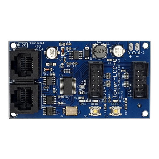
Overview The Tower LCC+Q (Layout Command & Control) interface provides a simple and easy way to connect between the NMRA LCC® CAN bus and the layout. The Tower LCC+Q may be connected at any convenient point on the NMRA LCC® CAN bus. - Page 5 Tower LCC+Q Image Tower LCC+Q Connectors Tower LCC+Q Manual Rev-b...
-
Page 6: About Lcc
(actual or imaginary) for use at some later time. In order to do logic operations The Tower LCC+Q node includes groups of internal memory items (called Variables) to remember the states that have resulted from the various past EventIDs. -
Page 7: Segment
1.1.3 Line Each Tower LCC+Q contains 16 I/O lines. Each line has the ability to watch for 6 events (consumers) and to send out 6 events. (producers) Each line has two registers. One register remembers the 'State' of the line. (on or off) The second register remembers the state of the 'Veto' option. -
Page 8: Producer (Input Function)
For example this would allow you to enable/disable fascia buttons for local control of a turnout by using the output events from a panel switch to control the veto. Tower LCC+Q Manual Rev-b... -
Page 9: Sample Mode
Several different I/O modules are now compatible with Sample mode. This allows you to connect both input modules and output modules at the same time on the same port. This can save costs by combining dissimilar functions on the same hardware. Tower LCC+Q Manual Rev-b... -
Page 10: Tower Lcc+Q Features
2 Tower LCC+Q Features • The Tower LCC+Q uses the CAN bus implementation of the NMRA LCC. • Communicates over the LCC CAN bus at 125Kb. • Support for a total of 16 Input/Output lines: • Up to 16 Input Lines. (internal pull-up termination on all lines) •... - Page 11 Tower LCC+Q Manual Rev-b...
-
Page 12: Line Details
• None • On (Line Activate), Off (Line Inactivate) • Change (Toggle) • Veto on (Active), Veto off (Inactive) • Gated On (Non Veto Output), and Gated Off (Non Veto Output) • Gated Change (Non Veto Output) Tower LCC+Q Manual Rev-b... -
Page 13: Producer (Input Function)
This might be used to build a realistic traffic light controller. Be careful with this option because it can create a lot of traffic continuously, especially if the function output is blinking rapidly. Tower LCC+Q Manual Rev-b... -
Page 14: Delay
Sample mode is automatically enabled if both output and input functions are enabled on the same line. Several different RR-CirKits I/O modules are now compatible with Sample mode. This allows you to connect both input modules and output modules at the same time on the same port. -
Page 15: Power And Serial Connections
4 Power and Serial Connections The Tower LCC+Q (16 Line I/O Board) has four connectors and four status indicators. Two of these connectors are for connections to the LCC bus network. The other two are used as connections to the I/O lines. This section covers the system connections consisting of the CAN bus port connectors, power connections, I/O port connections and Status indicators. -
Page 16: Power Connections
The Tower LCC+Q has two status indicators located near to the LCC connectors. The green ON status indicator shows the power status of the Tower LCC+Q itself. The red ACT (activity) indicator normally shows all data activity on the bus, and also any activity/error status during a boot loader firmware upgrade. -
Page 17: Setting Up Virtual Code Lines
Normally these are used to represent the track speed allowed at arrival to the next mast. This is based on the ‘Aspect’ shown by the mast. 4.5 Tower LCC+Q I/O Connector Wiring The two port connector's wiring is as follows. Note that the pin numbers and I/O line numbers are NOT the same, and actually run opposite to each other. -
Page 18: Getting Started
Tower LCC+Q node. Node Address: Each Tower LCC+Q has a single node address that is used for CDI programming on the layout. Each individual Tower LCC+Q has its node address imprinted on a label on the back side of the board. - Page 19 This is a helpful reminder that the change has not yet been stored into the board where it can take effect. Open the JMRI CDI Window Tower LCC+Q Manual Rev-b...
-
Page 20: Input/Output Configuration
5.5 Line (I/O Ports) The Tower LCC+Q has two 8 bit Input/Output ports for a total of 16 lines. Each port is normally configured to be either all Inputs, or all Outputs, to be compatible with the various RR-CirKits I/O modules. However each line may also be individually set as either input or output for special purposes. -
Page 21: Lines
(Sample Mode section 1.2) The Berrett Hill Touch Trigger is an example of a one line device. The Tower LCC+Q can also control both the indicator’s color, using consumers, and report the output, using producers in the same channel. -
Page 22: Indications
• Gated On (Not Veto Input) – Gated response to an input level change to ‘true’ • Gated Off (Not Veto Input) – Gated response to an input level change to ‘false’ • Cascade command – Responds to any output state change Tower LCC+Q Manual Rev-b... -
Page 23: Tower Lcc+Q Secondary Messages
• Output On (Function hi) – Responds to an output level change to ‘high’ • Output Off (Function lo) – Responds to an output level change to ‘low’ 5.3.6 Tower LCC+Q Secondary Messages In these examples there are no second or third messages being sent in the sense of our previous LocoNet products. -
Page 24: Tower Lcc+Q Stl Logic Overview
The STL for the Tower LCC+Q is a subset of the Siemens S7-x language. 6.1.0 Preface In addition to its 16 I/O lines, and virtual track code lines, the Tower LCC+Q also includes 32 logic operator groups. This logic is state driven, not event driven. To interface the logic with LCC EventIDs we provide two tables to convert Inputs and Outputs into their corresponding events. -
Page 25: Segment: Conditionals
2. there is a string of numbers that makes no sense, other than to show the maximum number of characters allowed per line. Once you have completed the compilation cycle (see section 6.2.3) you will see the following error code in the syntax messages. Tower LCC+Q Manual Rev-b... -
Page 26: The Language
You are responsible for entering the correct logic. 6.2 The Language The Tower LCC+Q programming language is based on a subset of the IEC 1131 IL (Instruction List) standard as used by Siemens in their STL language. This subset does not include any of the counters, variables (other than Boolean) nor any math functions, (that require variables other than true/false) that are normally included by Siemens in their version of STL. -
Page 27: The Variables
LCC EventIDs, nor create any network traffic. There are 128 possible input (I) variables and 128 possible output (Q) variables available on the Tower LCC+Q. These are grouped together 8 at a time simply for naming convenience. Tower LCC+Q Manual Rev-b... -
Page 28: The Compilation Cycle
Segment: ‘Syntax Messages’. Two EventIDs are also created, one for ‘Build Successful’ and the other for ‘Syntax Error/s’ To read the resulting messages you must first click on [Refresh] for each message. For example: Tower LCC+Q Manual Rev-b... - Page 29 4. The error is someplace in Logic 1, Line 1. An investigation reveals that the ‘Comment’ operator needs to be ‘//’ not just a single ‘/’. Correct this and redo steps 2. - 4. to see the results. Tower LCC+Q Manual Rev-b...
-
Page 30: The Program Cycle
A or O will set the /FC bit to 1 signaling to combine the current logic status with the next instruction. RLO - Result of Logic Operation The RLO bit stores the running logic state of the currently processing instructions. Tower LCC+Q Manual Rev-b... -
Page 31: Bit Logic Instructions
(red highlight) shows the operator position in the example. ‘/*’ and ‘*/’ are the open and close comment markers respectively. A - And Tower LCC+Q Manual Rev-b... - Page 32 /* Assign the result to Output var4.0 */ X - Exclusive Or Format X <Bit> Description X checks whether the state of the addressed bit is "1", and XORs the test result with the RLO. Tower LCC+Q Manual Rev-b...
-
Page 33: Nesting Expressions
O( - Or with Nesting Open Format Description O( (OR nesting open) saves the RLO and OR bits and a function code into the nesting stack. A maximum of seven nesting stack entries are possible.. Example Tower LCC+Q Manual Rev-b... - Page 34 RLO. The OR bit is also included if the function code is "AND" or "AND NOT". Statements which open parentheses groups: • A( And with Nesting Open • AN( And Not with Nesting Open • O( Or with Nesting Open Tower LCC+Q Manual Rev-b...
-
Page 35: String Termination
S (set bit) places a "1" in the addressed bit if the RLO = 1. Example M1.1 /* Set Memory 1.1 to 1. (True) */ 6.3.5 Change the Result of Logic Operation (RLO): NOT - Negate RLO • Format • Description NOT negates the RLO. Tower LCC+Q Manual Rev-b... -
Page 36: Edge Transition
SAVE save the RLO for use in the next statement */ 6.3.6 Edge transition: FN - Edge Negative • Format FN <bit> • Description FN <Bit> (Negative RLO edge) detects a falling edge when the RLO Tower LCC+Q Manual Rev-b... - Page 37 Q 4.0 for one program scan cycle. (20mS) M 1.0 = Q4.0 /* When a Positive edge is detected at Memory 1.0 */ /* Output = Q4.0 4.0 is set to true for one logic cycle */ Tower LCC+Q Manual Rev-b...
-
Page 38: Logic Control
6.4.2 The Jump Instructions You can use the following jump instructions to interrupt the normal flow of your program unconditionally: JU - Jump Unconditional • Format JU <jump label> Tower LCC+Q Manual Rev-b... - Page 39 /* Previous NOT True */ SET Q 1.0 JU EXIT /* Set aspect to Stop then Exit */ If previous was true */ APPR: SET Q 1.1 EXIT: /* Set aspect to Approach then continue to Exit */ Tower LCC+Q Manual Rev-b...
- Page 40 Note the change from the previous example where the conditional had to be inverted before checking in order to check for the inverted sense. The following jump instructions interrupt the flow of logic in your program based on the signal state of a bit in the status word: Tower LCC+Q Manual Rev-b...
-
Page 41: Logic Variables
6.5.1 Overview of different STL variable types • I – Input (Consumer) • Q – Output (Producer) • Y – Track Receiver • Z – Track Transmitter • M – Local Memory Tower LCC+Q Manual Rev-b... -
Page 42: Logic Operation
For example, if you are calculating train direction by using sensor pairs, then the sensors need to be spaced far enough apart to give longer than 20ms between activation at the highest train speeds allowed. Tower LCC+Q Manual Rev-b... -
Page 43: Segment: Logic Inputs
Signal aspects, turnout positions, and relay controls are typical outputs that you may have. “Q” (output) variables are typically used to control external devices, but are not necessarily limited to these. Tower LCC+Q Manual Rev-b... -
Page 44: Segment: Track Receiver
When using these values within a logic statement you manually add the “.0”, etc. to indicate the desired speed. The shorthand example above “Y0.0” means track circuit “Receiver Zero is Stop”. (see below for suggested speed values) Tower LCC+Q Manual Rev-b... - Page 45 (Stop) then the circuit is shorted out and thereby disabled. We needed a value that corresponds to this and have added “Stop” to the set. The actual speed values for each aspect name are a function of your railroad’s rule book. Tower LCC+Q Manual Rev-b...
-
Page 46: Segment: Track Transmitter
“Logic Output” (Q) entry to create matching EventID entries in order to place the information onto the LCC Bus. This is even true when referencing the I/O ports on the Tower LCC+Q node itself. All of the LCC EventIDs are outside of the logic engine itself. -
Page 47: Timer Variables
T1 A I 2.1 L W#2#10 SP T1 A I 2.2 R T1 A T1 = Q 4.0 AND I 2.0 Enable T1, And I 2.1 Load 10 seconds Start Pulse T1 AND I 2.2 Reset Load timer into Q 4.0 Tower LCC+Q Manual Rev-b... - Page 48 Example L W#2#10 T1 A T1 = Q 4.0 /* Previous RLO True */ Load 10 seconds then Start Pulse T1 AND T1 Load timer status into Q 4.0 SE Extended Pulse Timer Tower LCC+Q Manual Rev-b...
- Page 49 Example L W#2#10 T1 A T1 = Q 4.0 /* Previous RLO True */ Load 10 seconds then Start Retriggerable On-Delay T1 AND T1 Load timer status into Q 4.0 SF Off-Delay Timer • Format Tower LCC+Q Manual Rev-b...
-
Page 50: Timer Details
LW#2#480 or LW#3#48. It may not be written as LW#1#4800 nor as LW#0#48000 because #xyz may not exceed 999 intervals. Choosing the right Timer Following the loading of the desired timing value you must immediately Start the Tower LCC+Q Manual Rev-b... - Page 51 T3 with its preset value of W#2#480 when Input 1.5 transitions from "0" to "1", presuming that timer T3 is still running, and Input 1.0 is still at "1", otherwise it will have no effect. Tower LCC+Q Manual Rev-b...
-
Page 52: Stl Logic Operators
Bit logic Instruction SAVE Bit logic Instruction Save RLO in BR Register Start Timer On-Delay Timer Start Timer Extended Pulse Timer Bit logic Instruction Start Timer Off-Delay Timer Start Timer Pulse Timer Start Timer Retentive On-Delay Timer Tower LCC+Q Manual Rev-b... - Page 53 Bit logic Instruction Exclusive Or Bit logic Instruction Exclusive Or with Nesting Open Bit logic Instruction Exclusive Or Not Bit logic Instruction Exclusive Or Not with Nesting Open Tower LCC+Q Manual Rev-b...
-
Page 54: Track Circuits
To link these virtual code circuits use the CDI to copy the key from one track circuit to another. The EventID for the TX code set will always come from the transmitting node and be entered into the receiving node to avoid accidental reuse of EventID numbers from show to show. Tower LCC+Q Manual Rev-b... -
Page 55: Prototype Code Line
We can send either ‘Stop’ (5) or ‘Tumble down’ (6) as an indication. This simplifies the coding of APB signals. To limit the number of indication EventIDs to 16 we have omitted the ‘M’ code as being unnecessary. Tower LCC+Q Manual Rev-b... -
Page 56: Abs And Apb Signal Plus Other Examples
8 ABS and APB Signal plus other examples For examples of using logic to control signals see the Signal LCC manual. The Tower LCC+Q logic may be used to expand a Signal LCC logic table if more statements are required. To be determined. -
Page 57: Tower Lcc+Q Compatible Input/Output Cards
9 Tower LCC+Q compatible Input/Output Cards The RR-CirKits Tower LCC+Q and its compatible I/O modules are designed to be clipped into Tyco 3-1/4" Snap-Track® mounted to the bench work. (Snap-Track® is a plastic channel designed to mount PC cards to a chassis, not something to run trains on.) -
Page 58: Oib-8 (Opto Isolator Board - 8 Input)
By using the proper options on the Tower LCC+Q the SCSD-8 may also be used to control dual coil momentary switch machines. In 'Dual Coil' mode the output lines must be paired such that the pair of lines requires just single address pair. -
Page 59: Smd-8 (Stall Motor Driver - 8 Line)
Includes dual ribbon connectors with offset lines to allow easy connection as output 1-4, or output 5-8, of the Tower LCC, or other driver. The RB-4 input lines are active low so all lines on this Tower LCC+Q port should be configured appropriately. This inverted input mode matches most types of driver outputs, and the drive polarity may be easily switched either in the Tower LCC+Q configuration or by reversing the RB-4 output contacts. - Page 60 The BOB-S may be mounted to a panel or stringer using #4 or smaller screws and spacers. Tower LCC+Q Manual Rev-b...
-
Page 61: Trouble Shooting
If there is activity at the LCC Terminator blue LED, but no activity light at the Tower LCC+Q when events are sent, check the LCC wiring. If the command is seen in the LCC® monitor, but not in the command light, be sure that the command you are sending is configured to respond on this Tower LCC. -
Page 62: Boot Loader
Do NOT restore a configuration saved from an earlier firmware version. It will destroy your virtual track circuit information. If an update to your Tower LCC+Q firmware is needed, a program such as "Firmware Update" in JMRI version 5.4 or later is required. - Page 63 ‘Gold’ button as you power it up again. The gold LED should start flashing to indicate that it is in forced boot mode. This will likely be required after a failed upgrade attempt. Tower LCC+Q Manual Rev-b...
-
Page 64: Grounding And Isolation
12 Grounding and Isolation Unlike the LCC Buffer-USB, the Tower LCC+Q is not optically isolated from the LCC bus. This allows for possible ground loop problems between the LCC® and your layout accessory power supplies, so be sure to keep the ground connection to the Power-Point either isolated, or else in common with your layout power source. -
Page 65: Warranty Information
13 Warranty Information We offer a one year warranty on the Tower LCC+Q. This device contains no user serviceable parts. If a defect occurs, please contact RR-CirKits at: service@rr-cirkits.com for a replacement. Tower LCC+Q Manual Rev-b... -
Page 66: Fcc Information
Any modifications to this device voids the user's authority to operate under and be in compliance with these regulations. The actual measured radiation from the Tower LCC+Q is much lower than the maximum that is permitted by the FCC Rules, so it is unlikely that this device will cause any RFI problems.
Need help?
Do you have a question about the Tower LCC+Q and is the answer not in the manual?
Questions and answers