Table of Contents
Advertisement
Quick Links
Installation Guide
Revision-f
August 2020
Manual for Firmware Rev-C5
Tower LCC
LCC (Layout Command and Control
16 line Input Output board
This PDF is designed to be read on screen, two pages at a
time. If you want to print a copy, your PDF viewer should
have an option for printing two pages on one sheet of
paper, but you may need to start with page 2 to get it to
print facing pages correctly. (Print this cover page
separately.)
Advertisement
Table of Contents

Related Manuals for RR-CirKits Tower LCC

Summary of Contents for RR-CirKits Tower LCC
- Page 1 Installation Guide Revision-f August 2020 Manual for Firmware Rev-C5 Tower LCC LCC (Layout Command and Control 16 line Input Output board This PDF is designed to be read on screen, two pages at a time. If you want to print a copy, your PDF viewer should...
- Page 2 You can download an editable version of this document from http://www.rr-cirkits.com/manuals/Tower LCC-manual-f.odt...
-
Page 3: Copyright
Copyright This document is Copyright © December 2016-2020 by RR-CirKits, Inc.. You may distribute it under the terms of either the GNU General Public License, version 3 or later (http://www.gnu.org/licenses/gpl.html), or the Creative Commons Attribution License (http://creativecommons.org/licenses/by/3.0/), version 3.0 or later. -
Page 4: Table Of Contents
3.2 Power Connections..................12 3.3 Status Indicators.....................12 3.4 Blue/Gold Buttons and LEDs................12 3.4.1 Setting up Virtual Code Lines..............12 3.4.2 Master Clock Adjustment.................13 3.5 Tower LCC I/O Connector Wiring...............13 4 Getting Started......................13 4.1 CDI (Configuration Description Information)..........14 5 Input/Output Configuration...................15 5.1 Identification....................16 5.2 Node Identification..................16... - Page 5 8.9 BOB-S (Break Out Board – Screw Terminal)..........29 9 Trouble shooting....................29 9.1 Sanity Test......................29 9.2 Activity Test....................30 10 Boot Loader......................30 10.1 Boot Loader Upgrade...................30 10.2 Firmware Upgrade..................31 11 Grounding and Isolation..................32 12 Warranty Information..................32 13 FCC Information....................32 Tower LCC Manual Rev-f...
-
Page 6: Overview
The Tower LCC (Layout Command & Control) interface provides a simple and easy way to connect between the NMRA LCC® CAN bus and the layout. The Tower LCC may be connected at any convenient point on the NMRA LCC® CAN bus. -
Page 7: About Lcc
1 About LCC The NMRA LCC ® is a subset of the OpenLCB specifications created by the OpenLCB group for Layout Command and Control. http://www.openlcb.org/ NMRA LCC ® devices are controlled by events. Each event has a unique value that will never be repeated by any other LCC event in use anyplace on your system, ®... -
Page 8: Segment
1.1.3 Line Each Tower LCC contains 16 I/O lines. Each line has the ability to watch for 6 events (consumers) and to send out 6 events. (producers) Each line has two registers. -
Page 9: Producer
1.1.5 Producer Each producer event can be configured to trigger in one of 10 ways: • ‘Consumer on' (activate), 'Consumer off' (inactivate), are trigger options that allow you to create a new producer event based on a command to activate or inactivate the output. -
Page 10: Electrical Specifications
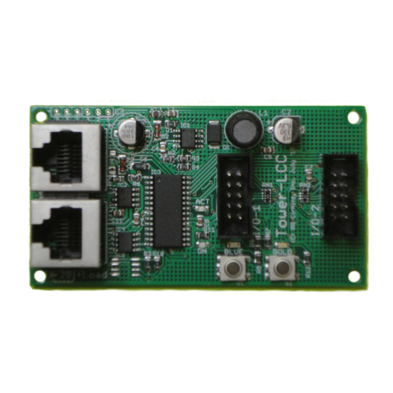
3 Power and Serial Connections The Tower LCC (16 Line I/O Board) has four connectors and four status indicators. Two of these connectors are for connections to the LCC bus network. The other two are used as connections to the I/O lines. This section covers the system connections consisting of the CAN bus port connectors, power connections, I/O port connections and Status indicators. -
Page 11: Can Lcc Compatible Connector
LCC power is supplied on Pin 7 and Pin 8. Power can be from +12VDC to +27VDC. The RR-CirKits LCC Power-Point delivers approximately 15VDC to the bus. The LCC connectors accept standard Ethernet style CAT5 (or better) cables. 4 pair cables are required by the Tower-LCC. -
Page 12: Power Connections
The Tower LCC has two status indicators located near to the LCC connectors. The green ON status indicator shows the power status of the Tower LCC itself. The red ACT (activity) indicator normally shows all data activity on the bus, and also any activity/error status during a boot loader firmware upgrade. -
Page 13: Master Clock Adjustment
Tower LCC node. Node Address: Each Tower LCC has a single node address that is used for CDI programming on the layout. Each individual Tower LCC has its node address imprinted on a label on the back side of the board. -
Page 14: Cdi (Configuration Description Information)
With the Deepsoft OpenLCB program you simply highlight a Protocol item to open it in a new window. Tower LCC Manual Rev-f Highlight ‘CDI’ to open it in a new window. -
Page 15: Input/Output Configuration
JMRI CDI tool or a similar program to set the Tower LCC configuration values. The following examples are using the JMRI CDI tool for the Tower LCC. Select the ‘LCC’ drop down list and click on 5 Input/Output Configuration Open the JMRI CDI Window... -
Page 16: Identification
5.3 Line (I/O Ports) The Tower LCC has two 8 bit Input/Output ports for a total of 16 lines. Each port is normally configured to be either all Inputs, or all Outputs, to be compatible with the various RR-CirKits I/O modules. However each line may be individually set as either input or output for special purposes. -
Page 17: Lines
(Sample Mode section 1.2) The Berrett Hill Touch Trigger is an example of a one line device. The Tower LCC can both control the indicator’s color using consumers and report the output using producers in the same channel. -
Page 18: Delay
Minutes. This allows for delays from 1ms. to over 41 days. Probably the extremes will never be required, but this gives you a good range to choose from. Actual accuracy is ½% or better. Millisecond times are calculated to the nearest 8 ms. Tower LCC Manual Rev-f... -
Page 19: Commands
Retrigger allows the time interval to be reset if the line state is set to ‘true’ again prior to the end of the delay time. If the line state is set to ‘false’ prior to the end of the delay time, then the output does not occur. -
Page 20: Indications
• Gated On (Not Veto Input) – Gated response to an input level change to ‘high’ • Gated Off (Not Veto Input) – Gated response to an input level change to ‘low’ 5.3.6 Tower LCC Secondary Messages In these examples there are no second or third messages being sent in the sense of our previous products. -
Page 21: Tower Lcc Logic
‘Variables’ allow decision making, even over power failures. To calculate this logic, the Tower LCC keeps a list of all events that can change the state of any variable. Any time one of these events is seen on the bus, a pass is made through the Logic table. - Page 22 Note: an adverse effect of this may result in the repeated sending of a default indication whenever any event for another mast in the same node is received. To reduce generation of spurious events, avoid using this option if possible. Tower LCC Manual Rev-f...
-
Page 23: Last (Single) Item
'Crack of Dawn' to control 'true' and 'High Noon' to control 'false'. However if your logic needs to be 'Its not morning' then use 'High Noon' to control 'true' and 'Crack of Dawn' to control 'false'. 6.0 Tower LCC Logic... -
Page 24: Logic Function
Any logic conditional may generate up to four events when it is true. Each of these four events may be; ignored with ‘none’, sent ‘Immediately’, or sent ‘After delay’. Each may be be conditioned with the True or False condition that sent it. Tower LCC Manual Rev-f... -
Page 25: Track Circuits
Track Circuits The prototype railroads have the need to send signal indication information from one signal to the next in order to calculate the proper aspects to display. These calculations are done locally, not at the dispatcher's office nor by some central computer. -
Page 26: Prototype Code Line
7.4 ABS and APB Signal examples For examples of using logic to control signals see the Signal LCC manual. The Tower LCC logic may be used to expand a Signal LCC logic table if more statements are required. Tower LCC compatible Input/Output Cards The RR-CirKits Tower LCC and its compatible I/O modules are designed to be clipped into Tyco 3-1/4"... -
Page 27: Bod-4 (Dcc Block Occupancy Detector - 4 Block Plus 4 I/O)
The CP version also includes dual turnout drivers. When used with the Tower LCC or Signal LCC boards there are also 4 general purpose I/O connections available using the Sample options. -
Page 28: Scsd-8 (Single Coil Solenoid Driver)
By using the proper options on the Tower LCC the SCSD-8 may also be used to control dual coil momentary switch machines. In 'Dual Coil' mode the output lines must be paired such that the pair of lines requires just single address pair. -
Page 29: Fob-A (Fan Out Board)
1-4, or output 5-8, of the Tower LCC, or other driver. The RB-4 input lines are active low so all lines on this Tower LCC port should be configured appropriately. This inverted input mode matches most types of driver outputs, and the drive polarity may be easily switched either in the Tower LCC configuration or by reversing the RB-4 output contacts. -
Page 30: Activity Test
If there is activity at the LCC Terminator blue LED, but no activity light at the Tower LCC when events are sent, check the LCC wiring. If the command is seen in the LCC® monitor, but not in the command light, be sure that the command you are sending is configured to respond on this Tower LCC. -
Page 31: Firmware Upgrade
Do NOT restore a configuration saved from an earlier firmware version. It will destroy your virtual track circuit information. If an update to your Tower LCC firmware is needed, a program such as "Firmware Update" in JMRI version 4.14 or later is required. -
Page 32: Grounding And Isolation
3 wire cable, and isolate them from each other via isolated equipment where necessary. 12 Warranty Information We offer a one year warranty on the Tower LCC. This device contains no user serviceable parts. If a defect occurs, please contact RR-CirKits at: service@rr-cirkits.com for a replacement. - Page 33 Any modifications to this device voids the user's authority to operate under and be in compliance with these regulations. The actual measured radiation from the Tower LCC is much lower than the maximum that is permitted by the FCC Rules, so it is unlikely that this device will cause any RFI problems.
Need help?
Do you have a question about the Tower LCC and is the answer not in the manual?
Questions and answers